Download
1 / 74
740 likes | 754 Views
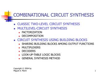
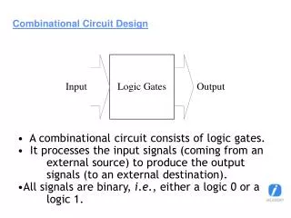
This lecture covers the data flow description of combinational circuit building blocks including fixed/variable shifters, rotators, multiplexers, decoders, and encoders using VHDL.

E N D
ECE 545 Lecture 6 Data Flow Description of Combinational-CircuitBuilding Blocks
Required reading • P. Chu, RTL Hardware Design using VHDL • Chapter 7, Combinational Circuit Design: • Practice
Fixed Shifters & Rotators ECE 448 – FPGA and ASIC Design with VHDL
Fixed Logical Shift Right in VHDL A(1) A(0) SIGNAL A : STD_LOGIC_VECTOR(3 DOWNTO 0); SIGNAL C: STD_LOGIC_VECTOR(3 DOWNTO 0); A(3) A(2) 4 A A >>1 L C C 4 ‘0’ A(3) A(2) A(1) ECE 448 – FPGA and ASIC Design with VHDL
Fixed Arithmetic Shift Right in VHDL A(1) A(0) SIGNAL A : STD_LOGIC_VECTOR(3 DOWNTO 0); SIGNAL C: STD_LOGIC_VECTOR(3 DOWNTO 0); A(3) A(2) 4 A A >>1 A C C 4 A(3) A(3) A(2) A(1) ECE 448 – FPGA and ASIC Design with VHDL
Fixed Logical Shift Left in VHDL A(1) A(0) SIGNAL A : STD_LOGIC_VECTOR(3 DOWNTO 0); SIGNAL C: STD_LOGIC_VECTOR(3 DOWNTO 0); A(3) A(2) 4 A A <<1 L C C 4 A(2) A(1) A(0) ‘0’ ECE 448 – FPGA and ASIC Design with VHDL
Fixed Rotation Left in VHDL SIGNAL A : STD_LOGIC_VECTOR(3 DOWNTO 0); SIGNAL C: STD_LOGIC_VECTOR(3 DOWNTO 0); A(3) A(2) A(1) A(0) 4 A A <<< 1 C C 4 A(2) A(1) A(0) A(3) ECE 448 – FPGA and ASIC Design with VHDL
Variable Rotators ECE 448 – FPGA and ASIC Design with VHDL
8-bit Variable Rotator Left 8 A 3 A <<< B B C 8 To be covered during one of the future classes ECE 448 – FPGA and ASIC Design with VHDL
Multiplexers ECE 448 – FPGA and ASIC Design with VHDL
2-to-1 Multiplexer s w 0 0 f w 1 1 f s w 0 0 w 1 1 (b) Truth table (a) Graphical symbol VHDL: f <= w0 WHEN s = '0' ELSE w1 ; or f <= w1 WHEN s = ‘1' ELSE w0 ; ECE 448 – FPGA and ASIC Design with VHDL
VHDL code for a 2-to-1 Multiplexer Entity LIBRARY ieee ; USE ieee.std_logic_1164.all ; ENTITY mux2to1 IS PORT ( w0, w1, s : IN STD_LOGIC ; f : OUT STD_LOGIC ) ; END mux2to1 ; ARCHITECTURE dataflow OF mux2to1 IS BEGIN f <= w0 WHEN s = '0' ELSE w1 ; END dataflow ; ECE 448 – FPGA and ASIC Design with VHDL
Cascade of twomultiplexers w 0 3 0 w 1 y w 2 1 1 s2 s1 VHDL: f <= w1 WHEN s1 = ‘1' ELSE w2 WHEN s2 = ‘1’ ELSE w3 ; ECE 448 – FPGA and ASIC Design with VHDL
VHDL design entity implementing a cascade of two multiplexers LIBRARY ieee ; USE ieee.std_logic_1164.all ; ENTITY mux_cascade IS PORT ( w1, w2, w3: IN STD_LOGIC ; s1, s2 : IN STD_LOGIC ; f : OUT STD_LOGIC ) ; END mux_cascade ; ARCHITECTURE dataflow OF mux2to1 IS BEGIN f <= w1 WHEN s1 = ‘1' ELSE w2 WHEN s2 = ‘1’ ELSE w3 ; END dataflow ; ECE 448 – FPGA and ASIC Design with VHDL
4-to-1 Multiplexer (a) Graphic symbol (b) Truth table s s s f s 0 1 0 s 1 w 0 0 0 w 00 0 w 0 1 1 w 01 1 w f 1 0 2 w 10 2 w 1 1 w 3 11 3 WITH s SELECT f <= w0 WHEN "00", w1 WHEN "01", w2 WHEN "10", w3 WHEN OTHERS ; ECE 448 – FPGA and ASIC Design with VHDL
VHDL code for a 4-to-1 Multiplexer entity LIBRARY ieee ; USE ieee.std_logic_1164.all ; ENTITY mux4to1 IS PORT ( w0, w1, w2, w3 : IN STD_LOGIC ; s : IN STD_LOGIC_VECTOR(1 DOWNTO 0) ; f : OUT STD_LOGIC ) ; END mux4to1 ; ARCHITECTURE dataflow OF mux4to1 IS BEGIN WITH s SELECT f <= w0 WHEN "00", w1 WHEN "01", w2 WHEN "10", w3 WHEN OTHERS ; END dataflow ; ECE 448 – FPGA and ASIC Design with VHDL
Decoders ECE 448 – FPGA and ASIC Design with VHDL
2-to-4 Decoder (b) Graphical symbol (a) Truth table w y w 1 3 w w y y y y En 1 0 3 2 1 0 w y 0 2 y 1 y 0 0 0 0 0 1 1 0 1 0 0 1 0 1 y En 0 1 1 0 0 1 0 0 1 1 1 1 0 0 0 Enw <= En & w ; WITH Enw SELECT y <= "0001" WHEN "100", "0010" WHEN "101", "0100" WHEN "110", "1000" WHEN "111", "0000" WHEN OTHERS ; x x 0 0 0 0 0 ECE 448 – FPGA and ASIC Design with VHDL
VHDL code for a 2-to-4 Decoder entity LIBRARY ieee ; USE ieee.std_logic_1164.all ; ENTITY dec2to4 IS PORT ( w : IN STD_LOGIC_VECTOR(1 DOWNTO 0) ; En : IN STD_LOGIC ; y : OUT STD_LOGIC_VECTOR(3 DOWNTO 0) ) ; END dec2to4 ; ARCHITECTURE dataflow OF dec2to4 IS SIGNAL Enw : STD_LOGIC_VECTOR(2 DOWNTO 0) ; BEGIN Enw <= En & w ; WITH Enw SELECT y <= "0001" WHEN "100", "0010" WHEN "101", "0100" WHEN "110", "1000" WHEN "111", "0000" WHEN OTHERS ; END dataflow ; ECE 448 – FPGA and ASIC Design with VHDL
Encoders ECE 448 – FPGA and ASIC Design with VHDL
Priority Encoder w w w w y y z 3 2 1 0 1 0 0 0 0 0 d d 0 0 0 0 1 0 0 1 - 0 0 1 0 1 1 - - 0 1 1 0 1 - - - 1 1 1 1 w 0 y y 0 w 1 w y 1 y <= "11" WHEN w(3) = '1' ELSE "10" WHEN w(2) = '1' ELSE "01" WHEN w(1) = '1' ELSE "00" ; z <= '0' WHEN w = "0000" ELSE '1' ; w 2 z w 3 ECE 448 – FPGA and ASIC Design with VHDL
VHDL code for a Priority Encoder entity LIBRARY ieee ; USE ieee.std_logic_1164.all ; ENTITY priority IS PORT ( w : IN STD_LOGIC_VECTOR(3 DOWNTO 0) ; y : OUT STD_LOGIC_VECTOR(1 DOWNTO 0) ; z : OUT STD_LOGIC ) ; END priority ; ARCHITECTURE dataflow OF priority IS BEGIN y <= "11" WHEN w(3) = '1' ELSE "10" WHEN w(2) = '1' ELSE "01" WHEN w(1) = '1' ELSE "00" ; z <= '0' WHEN w = "0000" ELSE '1' ; END dataflow ; ECE 448 – FPGA and ASIC Design with VHDL
Adders ECE 448 – FPGA and ASIC Design with VHDL
Adder mod 216 16 16 X Y S 16
VHDL code for an Adder mod 216 LIBRARY ieee ; USE ieee.std_logic_1164.all ; USE ieee.std_logic_unsigned.all ; ENTITY adder16 IS PORT ( X : IN STD_LOGIC_VECTOR(15 DOWNTO 0) ; Y : IN STD_LOGIC_VECTOR(15 DOWNTO 0) ; S : OUT STD_LOGIC_VECTOR(15 DOWNTO 0) ) ; END adder16 ; ARCHITECTURE dataflow OF adder16 IS BEGIN S <= X + Y ; END dataflow ;
16-bit Unsigned Adder 16 16 X Y + Cout Cin S 16 ECE 448 – FPGA and ASIC Design with VHDL
Operations on Unsigned Numbers For operations on unsigned numbers USE ieee.std_logic_unsigned.all and signals of the type STD_LOGIC_VECTOR OR USE ieee.numeric_std.all and signals of the type UNSIGNED and conversion functions: std_logic_vector(), unsigned() ECE 448 – FPGA and ASIC Design with VHDL
Signed and Unsigned Types Behave exactly like STD_LOGIC_VECTOR plus, they determine whether a given vector should be treated as a signed or unsigned number. Require USE ieee.numeric_std.all; ECE 448 – FPGA and ASIC Design with VHDL
VHDL code for a 16-bit Unsigned Adder LIBRARY ieee ; USE ieee.std_logic_1164.all ; USE ieee.std_logic_unsigned.all ; ENTITY adder16 IS PORT ( Cin : IN STD_LOGIC ; X : IN STD_LOGIC_VECTOR(15 DOWNTO 0) ; Y : IN STD_LOGIC_VECTOR(15 DOWNTO 0) ; S : OUT STD_LOGIC_VECTOR(15 DOWNTO 0) ; Cout : OUT STD_LOGIC ) ; END adder16 ; ARCHITECTURE dataflow OF adder16 IS SIGNAL Sum : STD_LOGIC_VECTOR(16 DOWNTO 0) ; BEGIN Sum <= ('0' & X) + Y + Cin ; S <= Sum(15 DOWNTO 0) ; Cout <= Sum(16) ; END dataflow ; ECE 448 – FPGA and ASIC Design with VHDL
Addition of Unsigned Numbers (1) LIBRARY ieee ; USE ieee.std_logic_1164.all ; USE ieee.numeric_std.all ; ENTITY adder16 IS PORT ( Cin : IN STD_LOGIC ; X : IN STD_LOGIC_VECTOR(15 DOWNTO 0) ; Y : IN STD_LOGIC_VECTOR(15 DOWNTO 0) ; S : OUT STD_LOGIC_VECTOR(15 DOWNTO 0) ; Cout : OUT STD_LOGIC ) ; END adder16 ; ECE 448 – FPGA and ASIC Design with VHDL
Addition of Unsigned Numbers (2) ARCHITECTURE dataflow OF adder16 IS SIGNAL Xu : UNSIGNED(15 DOWNTO 0); SIGNAL Yu: UNSIGNED(15 DOWNTO 0); SIGNAL Su : UNSIGNED(16 DOWNTO 0) ; BEGIN Xu <= unsigned(X); Yu <= unsigned(Y); Su <= ('0' & Xu) + Yu + unsigned('0' & Cin) ; S <= std_logic_vector(Su(15 DOWNTO 0)) ; Cout <= Su(16) ; END dataflow ; ECE 448 – FPGA and ASIC Design with VHDL
Addition of Unsigned Numbers (3) ARCHITECTURE dataflow OF adder16 IS signal Sum: STD_LOGIC_VECTOR(16 DOWNTO 0) ; BEGIN Sum <= std_logic_vector( unsigned('0' & X) + unsigned(Y) + unsigned('0' & Cin) ) ; S <= Sum(15 downto 0); Cout <= Sum(16) ; END dataflow ; ECE 448 – FPGA and ASIC Design with VHDL
Operations on Signed Numbers For operations on signed numbers USE ieee.numeric_std.all, signals of the type SIGNED, and conversion functions: std_logic_vector(), signed() OR USE ieee.std_logic_signed.all and signals of the type STD_LOGIC_VECTOR ECE 448 – FPGA and ASIC Design with VHDL
Multipliers ECE 448 – FPGA and ASIC Design with VHDL
Unsigned vs. Signed Multiplication Unsigned Signed 1111 1111 1111 1111 15 15 -1 -1 x x x x 11100001 225 00000001 1
8x8-bit Unsigned Multiplier 8 8 a b * c U 16
Multiplication of unsigned numbers LIBRARY ieee; USE ieee.std_logic_1164.all; USE ieee.std_logic_unsigned.all ; entity multiply is port( a : in STD_LOGIC_VECTOR(7 downto 0); b : in STD_LOGIC_VECTOR(7 downto 0); c : out STD_LOGIC_VECTOR(15 downto 0) ); end multiply; architecture dataflow of multiply is begin c <= a * b; end dataflow;
8x8-bit Signed Multiplier 8 8 a b * c S 16
Multiplication of signed numbers LIBRARY ieee; USE ieee.std_logic_1164.all; USE ieee.std_logic_signed.all ; entity multiply is port( a : in STD_LOGIC_VECTOR(7 downto 0); b : in STD_LOGIC_VECTOR(7 downto 0); c : out STD_LOGIC_VECTOR(15 downto 0) ); end multiply; architecture dataflow of multiply is begin c <= a * b; end dataflow;
8x8-bit Unsigned and Signed Multiplier 8 8 a b cu cs 16 16
Multiplication of signed and unsigned numbers LIBRARY ieee; USE ieee.std_logic_1164.all; USE ieee.numeric_std.all ; entity multiply is port( a : in STD_LOGIC_VECTOR(7 downto 0); b : in STD_LOGIC_VECTOR(7 downto 0); cu : out STD_LOGIC_VECTOR(15 downto 0); cs : out STD_LOGIC_VECTOR(15 downto 0) ); end multiply; architecture dataflow of multiply is begin -- signed multiplication cs <= STD_LOGIC_VECTOR(SIGNED(a)*SIGNED(b)); -- unsigned multiplication cu <= STD_LOGIC_VECTOR(UNSIGNED(a)*UNSIGNED(b)); end dataflow;
Comparators ECE 448 – FPGA and ASIC Design with VHDL
4-bit Unsigned Number Comparator 4 A A > B AgtB 4 B U AgtB <= '1' WHEN A > B ELSE '0' ; ECE 448 – FPGA and ASIC Design with VHDL
VHDL code for a 4-bit UnsignedNumber Comparator entity LIBRARY ieee ; USE ieee.std_logic_1164.all ; USE ieee.std_logic_unsigned.all ; ENTITY compare IS PORT ( A, B : IN STD_LOGIC_VECTOR(3 DOWNTO 0) ; AgtB : OUT STD_LOGIC ) ; END compare ; ARCHITECTURE dataflow OF compare IS BEGIN AgtB <= '1' WHEN A > B ELSE '0' ; END dataflow ; ECE 448 – FPGA and ASIC Design with VHDL
VHDL code for a 4-bit SignedNumber Comparator entity LIBRARY ieee ; USE ieee.std_logic_1164.all ; USE ieee.std_logic_signed.all ; ENTITY compare IS PORT ( A, B : IN STD_LOGIC_VECTOR(3 DOWNTO 0) ; AgtB : OUT STD_LOGIC ) ; END compare ; ARCHITECTURE dataflow OF compare IS BEGIN AgtB <= '1' WHEN A > B ELSE '0' ; END dataflow ; ECE 448 – FPGA and ASIC Design with VHDL
4-bit Unsigned Number Comparator 4 A AeqB AgtB 4 B AltB U
VHDL code for a 4-bit UnsignedNumber Comparator LIBRARY ieee ; USE ieee.std_logic_1164.all ; USE ieee.std_logic_unsigned.all ; ENTITY compare IS PORT ( A, B : IN STD_LOGIC_VECTOR(3 DOWNTO 0) ; AeqB, AgtB, AltB : OUT STD_LOGIC ) ; END compare ; ARCHITECTURE dataflow OF compare IS BEGIN AeqB <= '1' WHEN A = B ELSE '0' ; AgtB <= '1' WHEN A > B ELSE '0' ; AltB <= '1' WHEN A < B ELSE '0' ; END dataflow ;
VHDL code for a 4-bit SignedNumber Comparator LIBRARY ieee ; USE ieee.std_logic_1164.all ; USE ieee.std_logic_signed.all ; ENTITY compare IS PORT ( A, B : IN STD_LOGIC_VECTOR(3 DOWNTO 0) ; AeqB, AgtB, AltB : OUT STD_LOGIC ) ; END compare ; ARCHITECTURE dataflow OF compare IS BEGIN AeqB <= '1' WHEN A = B ELSE '0' ; AgtB <= '1' WHEN A > B ELSE '0' ; AltB <= '1' WHEN A < B ELSE '0' ; END dataflow ;
Arithmetic operations Synthesizable arithmetic operations: • Addition, + • Subtraction, - • Comparisons, >, >=, <, <= • Multiplication, * • Division by a power of 2, /2**6(equivalent to right shift)
Arithmetic operations The result of synthesis of an arithmetic operation is a - combinational circuit - without pipelining. The exact internal architecture used (and thus delay and area of the circuit) may depend on the timing constraints specified during synthesis (e.g., the requested maximum clock frequency).