Download
1 / 55
1.16k likes | 2.67k Views
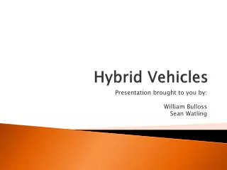
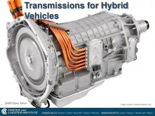
Transmissions for Hybrid Vehicles. 2009 Chevy Tahoe. Image courtesy of General Motors Corp. Manual transmissions and Hybrids. The only hybrid vehicle sold in the US with a manual transmission was the 2000 Honda insight

E N D
Transmissions for Hybrid Vehicles 2009 Chevy Tahoe Image courtesy of General Motors Corp.
Manual transmissions and Hybrids • The only hybrid vehicle sold in the US with a manual transmission was the 2000 Honda insight • Manual transmissions do not work well with hybrids as they must remain in gear as the vehicle is slowing down • To gain full advantage from regenerative braking the Insight driver needed to keep the clutch applied while slowing down so that the engine could be driven by the driveline while the IMA motor generated electricity • This is contrary to the way that most drivers of manual transmission cars drive their vehicles – they apply the clutch and coast to a stop
Light and Mild Hybrids • The electric motor/generator is connected to the engine crankshaft on a light or mild hybrid. • This allows a conventional automatic transmission to be used. • During regenerative braking driveline torque must be passed through the transmission, turning the crankshaft and allowing the motor / generator to generate electricity. • During regenerative braking roller clutches that normally allow the transmission to freewheel must be locked out. • The torque converter clutch must remain applied for the driveline torque to be transferred to the crankshaft.
Light and Mild Hybrids • In order for the motor/generator to receive torque from the driveline during regenerative braking the torque converter clutch and overrunning clutches must remained locked. • To reduce engine drag and maximize regenerative braking some systems deactivate cylinders during braking. Motor/Generator Torque Converter Clutch Overrunning Clutch
Conventional Automatic transmissions • A vehicle that has a start/stop function needs to be able to keep the transmission in gear and ready to accelerate the moment the gas pedal is depressed • The electrically driven hydraulic pump on this transaxle keeps hydraulic pressure applied to the clutches inside the transmission during engine stop mode Electrically driven pump Image courtesy of General Motors Corp.
CVT Transmissions • Continuously Variable Transmissions are ideal for mild hybrid applications. • CVT transmissions use metal belts and pulleys to transmit power through an infinite number of gear ratios. • A CVT transmission allows the engine RPM to stay at a constant speed as the vehicle accelerates and decelerates. Image courtesy of General Motors Corp. Saturn CVT Transaxle Image courtesy of General Motors Corp.
Mild Hybrid CVT Output pulley • Mild hybrids often use a mechanical CVT type transmission to optimize fuel economy • Gear reduction is accomplished by a multi-link steel belt running between two pulleys • The depth of the V-groove in the pulleys can be altered by changing the hydraulic pressure applied to one side of the pulley • The only gears used inside the transaxle drive reverse gear or are used to transfer torque from the output pulley to the differential Hydraulic piston Hydraulic piston Input pulley Image courtesy of General Motors Corp.
Acceleration RPM / MPH 4000 Conventional Transmission 3500 3000 CVT Transmission 2500 2000 Point where CVT transmission reaches lowest overdrive ratio 1500 1000 500 0 10 20 30 40 50 60 70 80 90 100
CVT Transmission Belt • A CVT transmission uses a metal belt running between two adjustable pulleys to achieve an infinite number of gear ratios. Input Pulley Output Pulley
CVT Pulleys • Two cones combine to make a single pulley. • The distance between the cones can be adjusted by a hydraulic cylinder. • As the distance between the cones decreases the belt must ride further away from the center – effectively increasing the diameter of the pulley. Moving Cone Fixed Cone
CVT Pulleys Input Pulley • To maintain belt tension the output pulley must mirror the change in the input pulley. • When the spacing between the cones of the input pulley becomes smaller the spacing between the cones of the output pulley must become larger by the same amount. Output Pulley
Gear Ratios • When the input pulley is at minimum diameter and the output pulley is at maximum diameter the transmission is at maximum reduction. Typically 2.5:1 Max Reduction • When the input pulley is at maximum diameter and the output pulley is at minimum diameter the transmission is at maximum Overdrive. Typically 0.4:1 Max Overdrive
CVT Drive Belt • The belt is made up of hundreds of ‘T’ shaped links that a held together by two highly flexible steel bands. • Unlike a rubber ‘V’ belt the metal belt transfers power by pushing through the belt – not by pulling.
CVTDrive Belt and Pulleys Output Pulley Drive Belt Input Pulley Forward/Reverse Clutch
CVT Pulley Actuator • A hydraulic piston applies pressure to the moving cone. • The piston is held inside the bore by spring tension. • As the hydraulic pressure increases, the moving cone is forced into the fixed cone. Hydraulic Pressure Feed
CVT Transmissions • A CVT transmission changes ratios by adjusting the spacing between two cones that form the ‘V’ pulley. • Moving the two cones together effectively increases the diameter that the belt contacts. • Moving the cones apart effectively decreases the pulley diameter.
CVT Transmissions Reverse Planetary Belt Flywheel Input Pulley Drum Output Pulley Drum Starting Clutch Valve Body Differential
Starting Clutch Flywheel And Damper • Honda hybrids do not use a torque converter. • A multi-disc hydraulic clutch is used to couple and decouple the transmission form the final drive. • To get the car rolling from a dead stop the TCM applies a PWM duty cycle that lightly applies the clutch. Once the vehicle begins to move at a speed that will allow the engine to engage the driveline without stalling the clutch is fully engaged. Starting Clutch Starting Clutch Solenoid TCM
Honda CVT Starting Clutch Belt Output Pulley Drum Flywheel Input Pulley Drum Damper Pressure Regulator Solenoid
Reverse Gear Ring Gear • Reverse can be accomplished by two methods: Planetary Carrier Sun Gear Driving Gear Planetary gearset Idler Gear Idler Gearset Driven Gear
Electronic CVT Motor/Generator #1 Motor/Generator #2 • The Electronic CVT transmission uses two electric motor/generators and a planetary gearset as a torque combining device
Two types of E-CVT • Toyota Single Mode system used by: • Toyota/Lexus • Ford • Nissan • Dual Mode hybrid system used by: • General Motors • BMW • Mercedes Benz • Chrysler
SingleModeE-CVT 2006 Ford Escape Hybrid • Toyota developed the single mode E-CVT for the original Prius. • Toyota now licenses it’s hybrid system technology to Ford and Nissan
Torque Combining Device • The single mode hybrid CVT uses a planetary gearset to combine torque from an ICE engine and two electric motor/generators.
Planetary Gearsets • The individual elements of the planetary gearset can be input, output or held. • How the elements are driving, driven or held determines what gear ratio and direction of rotation is produced. Ring Gear Planetary Carrier Sun Gear
Single Mode Transmission • Ring gear • Connected to the final drive • Also connected to MG2 • Rotates whenever the vehicle is in motion Ring Gear • Planetary carrier • Connected to the engine crankshaft • Rotates whenever the engine is running • Is effectively held whenever the engine is not running Planetary Carrier • Sun gear • Connected to MG1 • The sun gear and MG1 determine the gear ratio and vehicle speed Sun Gear
Single Mode Drive System Planetary Gearset MG2 MG1 Oil Pump Damper Transfer Chain Final Drive
Prius Transaxle Transfer Chain MG2 Damper Planetary Gearset MG1
Toyota Single Mode Transaxle Drive Chain Damper MG2 Oil Pump Coolant In/Out Planetary Gearset MG1
Transmission & Inverter Cooling System Reservoir and Pressure Cap Electric Water Pump Dedicated Radiator for Inverter and Motor / Generator
Transmission Cooling System • Note how the transaxle has 2 drain plugs. 2006 Highlander Hybrid Drain for Inverter / Transaxle coolant Drain for Transmission Fluid
Controls • Range Selector knob electronically signals Hybrid Control Module for operating range. • The ‘B’ range is used for engine braking on prolonged downhill driving. • Park switch activates the park servo motor that engages the parking pawl in the transmission. • There is no transmission control cable. All transmission controls are done electronically.
Single Mode inefficiency at highway speeds • The single mode system is less efficient at highway speeds than a conventional transmission. • At highway speeds MG2 generates electricity and MG1 uses that electricity to produce power. • In this process about 20% of the overall energy produced by MG2 is lost to heat in the motors and inverter. Inverter MG1 MG2
Dual Mode System • The dual mode transmission combines the low speed efficiency of the single mode system with the high speed efficiency of a conventional mechanical planetary system.
Dual Mode System • The dual mode system was a joint development project by engineers from: • General Motors • BMW • Mercedes Benz • Chrysler • The first vehicle to use this system is the 2008 Chevy Tahoe & 2008 GMC Yukon. • The basic system was developed in 1997 for GMC city busses – over 1000 of these are on the road.
Dual Mode Transmission • 3 Planetary Gearsets • 4 Multiple disc clutches Image courtesy of General Motors Corp.
Dual Mode Transmission Damper • The Dual Mode transmission has a damper unit and does not use a torque converter. • The damper drives an oil pump for high speed operation. • An electrically driven oil pump is used for low speed operation. Mechanical Oil Pump Electric Oil Pump
Dual Mode Transmission components MG2 MG1 • Two 60 KW [80 HP] electric motor / generators provide power for low speed electrical operation. Output Planetary Gearset Input Planetary Gearset Damper
Three Planetary Gearsets • The two electric motors are connected to elements of the front and center planetary gearsets
Four Hydraulic Clutches Multiple Disc Clutches Image courtesy of General Motors Corp.
Dual Mode Components Reaction Planetary Output Planetary Input Planetary MG1 MG2 Damper Driving Clutch C Holding Clutch D Driving Clutch A Holding Clutch B
Input Split Mode Clutch D Applied • Input split mode functions just like the single mode of the Toyota System • The two electric motors provide torque for low speed operation and the power of the ICE engine can be combined with the two motors to provide maximum torque for acceleration. • Hydraulic clutch ‘D’ [ 2nd gear] is needed to connect the two front planetaries to the output shaft.
Input Split Mode • In Input-Split mode the vehicle can operate under electric power or a combination of electric power and ICE power. • Under electric operation MG1 acts as a generator and MG2 acts as a motor. • Input-split mode uses 1st and 2nd gear fixed gear ranges. • The Input-Split mode usually functions at speeds between 0 and 30 MPH.
Compound Split Mode • Compound-Split mode provides 4 fixed gear ratios using multiple disc clutches and planetary gearsets. • Power from the engine is delivered directly to the four multiple disc clutches and two rear planetary gearsets.
Compound Split Mode A B C D
Compound Split Mode • Compound-Split mode provides greater efficiency than Input-split mode at highway speeds. • When running in the Compound-Split mode the electric motors can kick-in whenever additional torque is required. • Compound-Split mode usually begins at about 30 MPH. • When the vehicle is running in compound split mode the electric motors can be turned off.
Dual Mode System • The Duel Mode electrical system is essentially the same as the single mode system. • Since the Dual Mode system is more efficient a simple transmission cooler is sufficient for removal of excess heat from the electric motors. Inverter 12 volt Battery 300 volt Ni-MH Battery pack Dual Mode Transmission Image courtesy of General Motors Corp.