Download
1 / 22
230 likes | 425 Views
Introduction to Data Flow Modelling. The data flow approach to requirements determination in building a system for business use.

E N D
Introduction to Data Flow Modelling The data flow approach to requirements determination in building a system for business use. This type of computer systems is commonly called Transaction Processing System, which is the earliest use (1970’s to 1990’s) of computer technologies in businesses. Examples are: • Bank ATM (automatic teller machines) • Bank passbook update and printing • Point of sale cashier in supermarket • Payroll • Airline ticket reservation • Accounting packages • Buy/sell stocks, gold, foreign currencies etc. • Octopus
Transaction Processing Systems (Operational level) • A transaction is any business-related exchange e.g. payments to employees, sales to customers, payments to suppliers. • Transaction processing system (TPS) - an organized collection of people, procedures, software, databases, and hardware devices used to record completed business transactions. • TPS is the earliest use of computers to reduce labour costs by automating routine, repetitive, labour-intensive business procedures.
Software specification The process of establishing what services are required and the constraints on the system’s operation and development Requirements engineering process involves the following activities: Feasibility study (e.g. contract) Requirements elicitation and analysis Requirements specification Requirements validation
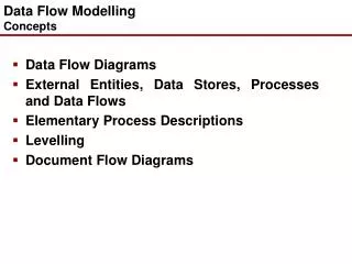
Introduction • Data Flow Modeling or diagram (DFDs) represents the flow of information around a system, the way it is changed, processed and stored and the ‘sources’ (sender) and ‘sinks’ (receiver) of information outside the computer system. • DFDs represent a situation from the viewpoint of the data (input or output); • DFDs - a technique to assist analysis of processes in the computer system.
Data-flow models • Show the processing steps as data flows through a computer system • Simple and intuitive notation that customers (non-technical, non-IT business people) can understand • Show end-to-end processing of data
Data-flow diagrams • may be used to show processing at different levels of abstraction from fairly abstract to fairly detailed • may also be used for architectural description showing data interchange between the sub-systems making up the system
Data Flow Diagrams • They show the overall data flow through a system and they do NOT show • control • order • time • errors • It is primarily a systems analysis tool used to draw the basic procedural components and the data that pass among them
Objectives of DFDs • to graphically document boundaries of a system; • to provide hierarchical breakdown of the system; • to show movement of information between a system and its environment; • to document information flows within the system; • to aid communication between users (or customers) and developers.
Context Diagram • A Context Diagram simply shows the system as a box, things external to the system as circles and the information flows into and out of the system. • It is usually regarded as a Level 0 DFD. • The context diagram can be a presentational aid for us to discuss the interfaces to and from the system without our audience getting concerned with the processes within the system.
Components of a DFD (1) Information Flow: • Data flows must be an input or output of a Process Box. • Physical flows are sometimes represented by a double or dotted line.
Components of a DFD (2) Process:
Components of a DFD (3) Source/Destination of Data, (External): • External entities are sources or sinks of data (people or organisations) that are lying outside the context of the system. • Source/Destination must be external to system, and must be a source or destination of input or output to/from the system. • Externals don't speak to each other.
Components of a DFD (4) Internal Data Store, (File): • Data stores can hold permanent, temporary, historical or extract data. • Files receive inputs and outputs only from Processes, NOT from Externals or other Files. • Identifier may be D or M.
Example • Fragment of DFD using all components
Hints for Drawing DFDs (1) For a diagram to be useful it must be at an appropriate level of detail: • avoid detail initially; • identify external entities - they provide the boundary; • identify main processes, then concentrate on data flows; • ensure enough data flows go into a process to perform transformations;
Hints for Drawing DFDs (2) • duplicate external entities and data store to improve clarity of diagram; • use meaningful names; • do not duplicate data flows; • be prepared to modify and re-draw; • prepare in conjunction with users.
Hints for Drawing DFDs (3) Duplicate external entities are usually represented by: Duplicate data stores are usually represented by:
Some remarks (1) From top to bottom: • Context Diagram is a zero level data flow diagram (0-DFD) • Next level is a first level data flow diagram (1-DFD) and builds on the Context Diagram by giving more detail
Some remarks (2) Naming Conventions • All processes must use a VERB and NOUN • All Data Flows must only use a NOUN • All files must be named: Invoice File (notice no underscore between the words-this is not a data flow)
Some remarks (3) Data Flow Diagram Conventions • Each context diagram must fit on one page • The process name in the context diagram should be the name of the system • Use unique names with each set of symbols • Do not cross lines • Use abbreviated identifications • Use a unique reference number for each process symbol