Download

1 / 42
420 likes | 484 Views
Digital Hadron Calorimetry Using Gas Electron Multiplier Technology. CALICE Meeting, NIU March 2005 Andy White (for the GEM-DHCAL group: UTA, U.Washington, Tsinghua U. ). Goals of DHCAL/GEM Project.

E N D
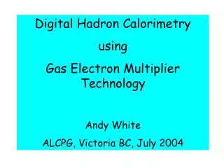
Digital Hadron Calorimetry Using Gas Electron Multiplier Technology CALICE Meeting, NIU March 2005 Andy White (for the GEM-DHCAL group: UTA, U.Washington, Tsinghua U.)
Goals of DHCAL/GEM Project • Design and construct a Linear Collider Detector calorimeter system based on GEM technology. • Build/study GEM systems. • Define operational characteristics of GEM system. • Understand DHCAL/GEM systems in terms of proposed LC detector design concepts. • Construct full size test beam module and beam test. • Use test beam results to develop PFA for GEM-based DHCAL. • Develop full DHCAL/GEM calorimeter system design.
Digital Hadron Calorimetry • Physics requirements emphasize segmentation/granularity (transverse AND longitudinal) over intrinsic energy resolution. • - Depth 4 (not including ECal ~ 1) + tail-catcher(?) • Assuming PFlow: • - sufficient segmentation (#channels) to allow efficient charged particle tracking. • - for “digital” approach – sufficiently fine segmentation (#channels) to give linear energy vs. hits relation • - efficient MIP detection (threshold, cell size) • - intrinsic, single (neutral) hadron energy resolution must not degrade jet energy resolution.
GEM - principle of operation 140mm 70mm GEM foil etching GEM field and multiplication From CERN-open-2000-344, A. Sharma
DHCAL/GEM Module concepts GEM layer slides into gap between absorber sheets Side plates alternate in adjacent modules Include part of absorber in GEM active layer - provides structural integrity
GEM system development Signal sharing and crosstalk studies
GEM/DHCAL signal sizes Goal:Estimate the minimum, average and maximum signal sizes for a cell in a GEM-based digital hadron calorimeter. Method: Associate the average total energy loss of the Landau distribution with the total number of electrons released in the drift region of the GEM cell.
Ionization in the GEM drift region A charged particle crossing the drift region will have a discrete number of “primary” ionizing collisions (ref. F.Sauli, CERN 77-09, 1977). An ejected electron can have sufficient energy to produce more ionization. The sum of the two contributions is referred to as the “total ionization”. In general, nT = nP * 2.5 Using Sauli’s table, we calculate nT = 93.4 ion pair/cm for Ar/CO2 80/20 mixture.
Characteristics of the Landau energy loss distribution The Landau distribution is defined in terms of the normalized deviation from the “most probable energy loss”, which is associated with the peak of the distribution – see the following slide. The average total energy loss occurs at about 50% of the peak (on the upper side). This is the point we associate with the quantity nT. In order to set a value for the minimum signal, we need to chose a point on the low side of the peak corresponding to a certain expected efficiency. From our GEM simulation, we find that we expect a 95% efficiency with a threshold at ~40% of the peak value – result from simulation (J.Yu, V.Kaushik, UTA)
Typical Landau curve Average total energy loss Threshold at 40% of peak Most probable energy loss
Energy Deposit MIP Efficiency GEM/DHCAL MIP Efficiency - simulation 95% Efficiency Energy Deposited (MeV)
Calculating our GEM signal levels Looking at the following slide for Ar/CO2 80/20 we see that the average total energy loss occurs at a signal size that is ~5x that for a minimum signal at 40% of the peak height on the low side of the peak. So then, if nT = 93.4 ion pair/cm, then we expect ~28 total electrons on the average per MIP at normal incidence on our 3mm drift region. This gives 5.6 electrons for the minimum signal. The gain we measured for our 70/30 mixture was ~3500, and we see a factor x3 for 80/20 (see following plot). Putting this all together, we expect Minimum signal size = 5.6 x 3,500 x 3 x 1.6 x 10-19 = 10 fC
Average Most probable Threshold
~ factor of 3 increase in signal at same voltage for 80:20 vs 70:30
Calculating our GEM signal levels We also expect: Most probable signal size ~20 fC Average signal size ~50fC These estimates are essential input to the circuit designers for the RPC/GEM ASIC front-end readout. The estimate of the maximum signal size requires input from physics (+background(s)) simulation…
GEM Efficiency Measurement Scin. Trigger
GEM efficiency measurement using cosmic rays Eff. = 94.6% after ensuring that cosmics must hit a pad % Threshold mv.
GEM Multiplicity Measurements Scin. Trigger
GEM Multiplicity Measurement • 9-pad (3x3) GEM Chamber – double GEM • Ar/CO2 80:20 • HV = 409V across each GEM foil • Threshold 40mV -> 95% efficiency • Sr-90 source/scintillator trigger • -> Result: Average multiplicity = 1.27
Exploiting the Time Structure of Energy Depositions in HCal ? • Hadronic signal has a time-distributed structure: • -> , K, p,… prompt signal • -> neutrons – delayed deposition(s) – if active medium is sensitive to neutrons • Integrated energy deposition? • Can we exploit this structure?? • Why? For complex energy deposition pattern -> time separation could reveal e.g. neutron component -> do NOT add these depositions to charged clusters, which would lead to mis-measurement. • - Direct neutrons vs. shower neutrons?
Exploiting the Time Structure of Energy Depositions in HCal ? • What are the fluctuations (in time) of the prompt vs. delayed depositions from shower to shower? • If the fluctuations are not too large, what precision do we need/can we achieve on the timing? • How do we implement the timing? • What is the time structure for gaseous calorimeters (vs. e.g. scintillator)? • Is it worth doing? Results vs. extra cost? • Need some simulation studies…? WORK!
Plans for next GEM assemblies • Produce and use larger GEM foils. • Intermediate step towards full-size foils for test beam. • Present 3M process allows ~30cm x 30cm foil production. • Order has been placed for foils – delivery in 1-2 months. • Assemble 5 layers of DGEM chambers – Spring 2005.
Cosmic stack using Double GEM counters Fermilab beam chamber DGEM 30cm x 30cm DGEM Readout system design being studied by U.Washington DGEM DGEM DGEM Fermilab beam chamber
Cosmic stack using Double GEM counters • Single cosmic tracks. • Hit multiplicity (vs. simulation) • Signal sharing between pads (e.g. vs. angle) • Efficiencies of single DGEM counters • Effects of layer separators • Operational experience with ~500 channel system • Possible test-bed for ASIC when available – rebuild one or more DGEM chambers.
T2K large GEM foil design (Close to COMPASS(CERN) foil design)
T2K large GEM foil design • Institutes cooperating on foil production: • U. Victoria BC (Canada) (T2K and LC TPC) • U. Washington (DHCAL) • Louisiana Tech. U. (LC TPC) • Tsinghua U. (DHCAL) • IHEP Beijing (GEM development) • U. Texas Arlington (DHCAL) • (share cost of masks, economy of scale in foil production)
305mm x 305mm layer Trace edge connector -> Fermilab 32 ch board – new production by Fermilab PPD Electronics (10 x 10) – 4 = 96 pad active area
Development of large-scale GEM layer for final test beam stack ~1m Test beam stack will be 1m3, with 40 active layers each ~8mm thick between steel absorber plates. 305mm GEM strip from 3M roll
GEM foils for test beam module • Ongoing discussions with 3M Corporation: research into process modification for “long” foil production: 500 ft reel • Repeat 3 x ~30cm x 30cm frame • Small gaps -> locate spacers • 240 long foils needed for test beam module • Foil production second half of 2005
Readout/ASIC development (UTA) • Specification of GEM signals (already discussed) • Increased signal sizes from changes in gas mixture • HSPICE simulation: • -> Software set up at UTA • -> A LOT of bureaucracy to get a MOSIS commercial license ! • -> Files set up • -> Working with UTA/EE faculty/grad. Student • - first results 1-2 weeks • - do not expect any surprises – confirm response to GEM signals
GEM detailed simulation • Garfield/Maxwell simulation of DGEM structure • Study: • Signal size/variation • Time structure of GEM charge pulse -> HSPICE • Signal spatial distribution (for TB comparison) • Effect(s) of E B on electron trajectories • - Two UTA undergraduates working on simulation
Maxwell/Garfield simulations of GEM detector Maxwell Next: Garfield
Particle/module simulation Talk by Jae Yu in Simulation and Reconstruction • Initial single particle and PFA studies concluded by two (now graduated!) MS students. • Further PFA work planned for Spring 2005 with new students. • UTA part of US/global(?) effort to produce full-scale PFAs . • Preparation for comparisons with test beam data. • Discussions with UT Dallas on joining simulation work (shower library work already started) – may also have students help with test beam module assembly. • Also plans to work on benchmark physics processes relevant to calorimeter performance studies.
DHCAL/GEM plans • Spring 2005 • Stack of DGEM chambers – cosmic studies • Long foil development with 3M Corp. • Summer/Fall 2005: • Initial long foil production and testing • Winter 2005/6 • Production of long foils for test beam module • Assembly of 40 DHCAL/GEM ~1m2 active layers • - 2006 • Full DHCAL/GEM module ready for beam tests.