Download
1 / 47
470 likes | 562 Views
Development of a state-of-the-art Digital Hadron Calorimeter utilizing Gas Electron Multiplier (GEM) technology, aiming for robust and low-cost implementation in high-energy physics experiments. The project involves understanding, designing, and testing large-scale GEM active layers for enhanced particle tracking and energy measurement. Recent studies focus on minimizing crosstalk for accurate hit detection and signal processing. The construction of GEM-sensitive layers involves optimizing materials, structural integrity, and gas volume maintenance while ensuring ease of assembly. Collaboration with various institutions ensures innovation in GEM foil production for mass-scale prototypes.

E N D
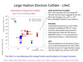
Digital Hadron Calorimetry using Gas Electron Multiplier Technology Andy White ALCPG, Victoria BC, July 2004
GEM/DHCAL development • Started with Research Enhancement Grant from UTA. • Supported by U.S. Department of Energy ADR and LCRD programs. • Important contributions from UTA Electrical Engineering, and UTA Computer Science Engineering. • Working with ANL HEP DHCAL/RPC group on readout electronics. • Working with CALICE collaboration.
Digital Hadron Calorimeter Development Linear Collider calorimetry development path at UTA: - Motivated by the physics potential! - Can digital + energy flow approach work ?? - Gas Electron Multipliers offer robust/low- cost/flexible technology to implement digital calorimetry STEPS: - Understand/operate GEM systems (done) - Develop GEM/DHCAL design (done) - Build/test large-scale GEM active DHCAL layer(s) - Develop full calorimeter design for test beam stack
140mm 70mm GEM foil etching GEM field and multiplication From CERN-open-2000-344, A. Sharma
Double GEM schematic Create ionization Multiplication Signal induction From S.Bachmann et al. CERN-EP/2000-151
Embeded onboard readout Ground to avoid cross-talk Design for DHCAL using Triple GEM
GEM/DHCAL cross-talk studies • - High digital “hit” efficiency essential for tracking charged particles in/through calorimeter. • plusminimal crosstalk to reduce confusion and mistakes in track following, pattern recognition. • Need crosstalk information to set threshold(s) for “hit” definition. • Examine hits from source particles in prototype on two adjacent pads. • Study nature of crosstalk signal with generated signals.
Recent cross-talk studies Pad examined for crosstalk Main pad UTA GEM/DHCAL prototype
UTA GEM Calorimeter prototype - typical signal Single cosmic event: upper = trigger, lower = preamp output
Crosstalk study Signal generator scope Insulator Copper pads
Crosstalk simulation (pulse generator) Study by Dr. Jia Li
Bigger pads = larger effect BigPad
…and vice-versa SmallPad
Effect of gap between adjacent pads Large Gap
Effect of gap between adjacent pads Small Gap
Effect of sharing signal between adjacent pads Trigger=252 Thr.=110mV, V=2000V.
Development of module concepts TESLA – HCAL Layout
DHCAL/GEM Module concepts GEM layer slides into gap between absorber sheets Side plates alternate in adjacent modules Include part of absorber in GEM active layer - provides structural integrity
Development of GEM sensitive layer Requirements: - minimize overall thickness - develop robust design - maintain 1mm, 3mm gaps in GEM structure - maintain active layer flatness – absorber slice - minimize “dead” boundary areas - maintain integrity of gas volume - design for ease of construction!
Development of GEM sensitive layer Absorber strong back Gas inlet/outlet (example) Cathode layer 3 mm Non-porous, double-sided adhesive strips 1 mm 1 mm 9-layer readout pc-board Anode(pad) layer Fishing-line spacer schematic (NOT TO SCALE) GEM foils
Development of GEM sensitive layer - Identified materials for layer construction - Specified interlayer spacings/spacers - Tried out assembly ideas - Built large (1ft x 2ft) mechanical prototypes - Iterating on assembly procedures - Specify/document final procedure prior to assembly of large, working active layer(s).
Details of GEM active layer construction (Tests using Kapton foil only for now)
Coating the absorber slice with adhesive for the cathode layer
Stretching the “GEM” layer with frame Note the need to be able to grip the edges of the kapton (but not the copper)
One form of 3mm spacer 3mm side walls and spacers installed
1mm side walls installed plus spacers and gas in/outlets Gas in/oulet
Final “GEM” foil installed, “PC board” installed, and whole assembly weighted
Development of large-scale GEM layer • Original plans were to use “existing” roll of 3M 10cm x 10cm foils… • However, the roll no longer exists! • Discussions on new run to produce what we actually need. • Several other customers for GEM foils for various studies (La Tech., U.Washington, IHEP-Beijing,…)
3M GEM foil production • Aim for 3 GEM foil strips/layer for ~1m3 prototype. • Need subdivision of GEM’s into separate voltage segments – minimal “no-copper” gap. • Other issues: • - use of Mylar for masks -> hole “slewing” • => glass phototool better but more costly • - pattern repetition/kapton gap for gripping edge • - New layout (with 15cm x 15cm subunits -> U.W. etc.)
Mass Production is based on a 3M Proprietary Flex Circuit Manufacturing Technique • 3M Microinterconnect Systems Division Reel-to-reel process, rolls of 16”’x16” templates of detachable GEMs in any pattern. Optional processes possible. • First batch of 1,980 GEMs recently produced. Low cost per unit! (~2 USD/GEM not counting R&D) • Two fabrication techniques (additive, substractive) tested. Reel to reel flex circuit manufacture in clean room conditions Single roll of ~1,000 GEMS hep-ex/0304013
3M GEM foil – new layout (detail) Gap in copper (both sides) for HV sector isolation Issue: providing copper-free strip to grip GEM layer
3M GEM foil production - issues • Quotation - $10K for glass phototool • cost per length of roll or per 15cm x 15cm unit? • Refine layout…develop cost sharing with other users • Specify QC at 3M and UTA – physical inspection, standing current (nA),… • Delivery?
GEM/DHCAL test beam stack issues GEM active layer – three sections • Minimizing walls • Joining GEM foils(?) • One strongback/layer? • Gas flow/supports (post vs. line) • 3 PCB’s or single pad layers? 305mm GEM strip from 3M roll …progress towards test beam design
Conclusions • Progress on understanding prototype signals and associated crosstalk. • Progress on large-scale GEM active layers. • Working with ANL/Fermilab on readout electronics (GEM mods to RPC design). • Working with 3M Corp. on GEM foil production. • Issue now is the funding/timescale for test beam stack.