Download
1 / 14
140 likes | 322 Views
Development of Gas Electron Multiplier Detectors for Muon Tomography. M. Abercrombie, A. Quintero, A. Menendez, K. Gnanvo, M. Hohlmann Physics and Space Science Department Florida Institute of Technology. Overview. Why GEMs? How GEMs work Assembly process Improvements. Why GEMs?.

E N D
Development of Gas Electron Multiplier Detectors for Muon Tomography M. Abercrombie, A. Quintero, A. Menendez, K. Gnanvo, M. Hohlmann Physics and Space Science Department Florida Institute of Technology M. Abercrombie - Florida Academy of Sciences - March 19, 2010
Overview • Why GEMs? • How GEMs work • Assembly process • Improvements M. Abercrombie - Florida Academy of Sciences - March 19, 2010
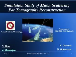
Why GEMs? • Compact design, versatile • Better spatial resolution than similar techniques (50-100 µm) • Relatively low cost • Uses naturally occurring, ubiquitous cosmic ray muons, easily penetrate high z materials • Well suited for muon tomography of potential nuclear contraband. M. Abercrombie - Florida Academy of Sciences - March 19, 2010
GEM Foils • GEM foils are made of a thin sheet of Kapton covered on both sides by copper • High density of tiny, chemically etched holes (~100 per mm2) • Foils stretched, framed, and glued; delicate and tedious process M. Abercrombie - Florida Academy of Sciences - March 19, 2010
Testing the Foils • Cleanroom • N2 gas flow • Voltage of 500V applied • Expect a leakage current of less than 5nA Image taken at CERN M. Abercrombie - Florida Academy of Sciences - March 19, 2010
How GEMs Work • Multiple foils stacked inside the detector • Sealed and put under Ar/CO2 gas mixture • Voltage applied to the foils creates a uniform electric field between foils M. Abercrombie - Florida Academy of Sciences - March 19, 2010
How GEMs Work • Muon ionizes the Ar/CO2 gas in the detector • Electrons from ionization process move toward the readout plane • Accelerated by high electric field, excites more electrons • Cascade of electrons • Readout in 2 dimensions M. Abercrombie - Florida Academy of Sciences - March 19, 2010
Our Set Up at Florida Tech • HV Power Supply • HV Circuit Board • 10 cm x 10 cm detector • Preamp • Oscilloscope • Gas Flow M. Abercrombie - Florida Academy of Sciences - March 19, 2010
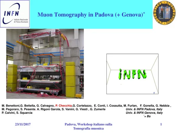
Our Set Up at CERN • Prototype for a Muon • Tomography station • determine incoming and • outgoing paths • angle of deflection gives • target composition • Four 30 cm x 30 cm GEM • detectors • 3 cm x 3 cm x 3 cm target M. Abercrombie - Florida Academy of Sciences - March 19, 2010
Results from CERN: Gain Curve • Gain defined as ratio of collected charges at readout to primary charge • Logarithmic behavior M. Abercrombie - Florida Academy of Sciences - March 19, 2010
Results from CERN: Uniformity Test • Test for consistent readout across the detector 7 6 5 4 3 2 1 M. Abercrombie - Florida Academy of Sciences - March 19, 2010
Results from CERN: Spectra • Energy spectrum of Cu X-rays in blue • Cosmic ray muon pulse height distribution in red (5 hours) M. Abercrombie - Florida Academy of Sciences - March 19, 2010
Improvements • Goal: Avoid tedious framing procedure • How: Use honeycomb spacers between the foils • will ensure that the GEM foils are flat • will not require that the foils be framed M. Abercrombie - Florida Academy of Sciences - March 19, 2010
Future Work • Obtain a signal with our 10 cm x 10 cm detector • Test the performance of honeycomb spacers between foils • Construction of a 30 cm x 30 cm detector with honeycomb spacers Learn more at: http://research.fit.edu/hep_labA/ M. Abercrombie - Florida Academy of Sciences - March 19, 2010