Download

1 / 19
190 likes | 213 Views
This study explores a possible scheme for positron production in the Compact Linear Collider (CLIC) using undulator technology. Numerical simulations are conducted to analyze the effect of undulator parameters and accelerating gradient on the yield. The optimization of the Orbit Modulation Dipole (OMD) for maximum yield is also investigated.

E N D
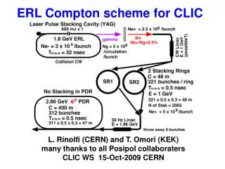
Preliminary Study on CLIC Undulator Positron Scheme Wei Gai, Wanming Liu @ ANL John C. Sheppard @ SLAC Louis Rinolfi @ CERN Positron Collaborating Meeting, ANL Sept. 17-19, 2007
Outline • A possible CLIC undulator scheme e+ source • Numerical Simulation on the effect of undulator parameter and accelerating gradient • Optimizing OMD for yield • Summary
To the IP e- beam Cleaning chicane Ti alloy e+ e+ 250 GeV 2.2 GeV NC Linac 450 m A possible CLIC scheme for polarized e+ Pre-Injector Linac G = 12 MV/m E = 200 MeV fRF = 1.5 GHz B = 0.5 T Injector Linac G = 17 MV/m E = 2.424 GeV f RF = 1.5 GHz f rep= 50 Hz Undulator K = 0.75 λu = 1.5 cm L = 100 m
Main beam parameters comparison At the entrance of the Main Linac for e- and e+
Numerical Simulation on the effect of undulator parameter and accelerating gradient • Drive e- beam energy: 250GeV • Undulator K: 0.75 and 0.5 • Undulator period: 1.5cm and 1.3cm • Length of undulator: 100m • Drift to target: 450m • Accelerator gradient and focusing: 12MV/m to 80MV/m for beam energy <250MeV, 0.5T background solenoid field focusing; for 250MeV to 2.4GeV, 25MV/m with discrete FODO set. • OMD: 7T-0.5T in 20cm; 10T-0.5T in 20cm • Photon collimator: None • Target material: 0.4 rl Titanium, immersed and non-immersed • Yield is calculated as Ne+ captured/Ne- in drive beam. • Positron capture is calculated by numerical cut using damping ring acceptance window: +/-7.5 degrees of RF(1.3GHz), ex+ey<0.09p.m.rad,1% energy spread with beam energy ~2.4GeV
Yield of cases with immersed target • For immersed case, the OMD field is 7T on the surface of target and decrease adiabatically down to 0.5T in 20cm. • We considered helical undulators with K=0.75 and 0.5, lu = 1.5cm and 1.3cm.
Yield of cases with Non-immersed target • For non-immersed target, the OMD field is about 0 on the surface of target and ramp up to over 7T or 10T in 2cm and then adiabatically decrease down to 0.5T in 20cm. • We considered helical undulators with K=0.75 and 0.5, period lu = 1.5cm and 1.3cm.
Using gradient higher than 50MV/m doesn’t help much on the yield for either immersed and non-immersed cases. • For non-immersed target, increasing the OMD field doesn’t necessarily increase the yield because of the associated higher transverse B field. • For low polarization e+ source, yield of 1.5 can be achieved by choosing undulator with K=0.75, lu=1.5cm; using non-immersed target and using accelerator gradient >24MV/m.
Optimizing OMD for yield • Drive e- beam energy: 250GeV • Undulator K: 0.75 • Undulator period: 1.5cm • Length of undulator: 100m • Drift to target: 450m • Accelerator gradient and focusing: 50MV/m for beam energy <250MeV, 0.5T background solenoid field focusing; for 250MeV to 2.4GeV, 25MV/m with discrete FODO set. • OMD: Non immersed, ramping distance 2cm • 1)7T-0.5T and 5T-0.5T, the thickness varies from 15cm to 80cm in 5cm steps; • 2) the thickness fixed at 20cm, B0-0.5T, B0 varies from 1 T to 10T • Photon collimator: None • Target material: 0.4 rl Titanium, non-immersed • Yield is calculated as Ne+ captured/Ne- in drive beam. • Positron capture is calculated by numerical cut using damping ring acceptance window: +/-7.5 degrees of RF(1.3GHz), ex+ey<0.09p.m.rad,1% energy spread with beam energy ~2.4GeV
Optimum length of OMD 20 cm is the optimum length for B0=5T
Optimum B0 of OMD (non-immersed case) 4T ~ 5T is the optimum