Download
1 / 21
210 likes | 338 Views
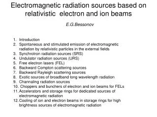
Undulator-based and Crystal-based Gamma Radiation Sources for Positron Generation. A. P. Potylitsyn Tomsk Polytechnic University, Tomsk, Russia. Conventional positron sources.

E N D
Undulator-based and Crystal-based Gamma Radiation Sources for Positron Generation A. P. Potylitsyn Tomsk Polytechnic University, Tomsk, Russia
Conventional positron sources Positrons are generated from showers produced by an initial electron beam in amorphous target with thickness ~ L0 (L0 – radiation length). Target thermal damage is the key problem.
Undulator – based scheme: - long undulator (~ 100 m); - electron energy (> 100 GeV); - mean photon energy (< 20 MeV); - amorphous converter (~ 0.5 L0). Advantages: - low energy deposition in converter; - good positron emittance.
Alternative approach to obtain intense photon source is using an oriented crystal target (“solid – state undulator”) Two radiation mechanisms – channeling radiation and coherent bremsstrahlung (CBS): There are two possible schemes: single converter hybrid target
First application of a W crystal positron source at the KEK B factory thickness 10 mm thickness 14 mm
The main spectral characteristics Bremsstrahlung (BS): radiation losses in a target ΔEBS (t/L0)E0 (t≤X0), t/L0 – target thickness (in units L0), E0 – electron energy. The mean photon energy for BS: < EBS> ΔEBS / <NBS>, <NBS> - mean number of emitted BS photons per electron 0=E0/mc2, ħɷp – plasmon energy For targets from W ɷp = 70 eV< EBS>~ 0.1 E0; For E0 = 1 GeV < EBS>~100 MeV
Channeling radiation (ChR) V0 potential of axis, as screening radius, ƛ electron compton wavelength. For <111> axis of Si target and E0 ~ 1 GeV < EChR>~15 MeV For <111> W < EChR>~40 MeV
Coherent bremsstrahlung (CBS) θ – orientation angle , d – interplanar destance. For a thick monocrystalline target For t =10 mm, Si <111>, E ~ 1 GeV <ECBS> ~ 50 MeV
Radiation losses in a crystalline target ΔE= ΔEBS+ΔEcry
Photon multiplicity More real estimation and simulation of a mean photon number (photon multiplicity) from oriented thick crystalline target is a very difficult task. There are much more troubles to measure such a characteristic in an experiment. In the experiment [M.D. Bavizhev et al. Sov. Phys. JETP, V.68 (1998) 803] authors had measured energy losses from e- with E0 = 10 GeV for Si <111> targets with thickness t = 0.8 mm and 3.0 mm. From Monte-Carlo simulations they have obtained 0.8 mm <Ncry>=1.8 ph/e- 3.0 mm <Ncry>=5.4 ph/e- The model of Baier et al. <N>=24 ph/e- The contribution from BS process is much less: 0.8 mm <NBS> 0.9·10-3 ph/e- 3.0 mm <NBS> 3.2·10-3 ph/e-
For a photon multiplicity <N> >> 1 this value can be estimated [A. Kolchuzhkin, A. Potylitsyn NIMB 173 (2001) 126] from energy losses <N> <Q>2 /2, <E> ΔE/<N>, where <Q> is the mean value of radiation losses, is distribution variance, ΔE – total energy losses. From such an estimation for 3 mm Si target: <Q> = 2.3 GeV, 1.1 GeV, ΔE 800 MeV (~0.08E0), <N> 4 ph/e-, <Ecry> 200 MeV.
Diamond target E0=4.5 GeV diamond t=10 mm (t/L0=0.08) Fit: <Q> = 1660 MeV = 536 MeV ΔE = 1300 MeV (~0.3E0) The estimation of multiplicity: <Ncry> 10 ph/e- <E> 130 MeV Let’s remember experiment [R. Avakian, A.E. Avetisyan, R.A. Asatryan et al., Sov. Tech. Phys. Lett., V.14 (1988) 395] One can expect a multiplicity <Ncry> > 10 ph/e- for Si target with thickness ~ 20 mm and E0 ~ 10 GeV.
UR “flat spectrum” Emax Photon number spectrum of UR from 150 GeV e beam Positron yield Estimation of positron yield from a converter with thickness t/L0. The simplest case for photon spectrum – “flat” one: <N> is a multiplicity. Radiation losses:
A positron spectrum produced by photon with energy E in the converter with thickness t [A.P. Potylitsyn NIMA 398 (1997) 395] - screening parameter. After convolution with “flat” photon spectrum For <N> = 2 ph/e-, t=L0, E max= 21 MeV estimation (*) gives dN+/dε+= 0.02 for ε+= 10 MeV. Flottmann’s estimation [K.Flotmann. Preprint DESY 93-161, Nov.1993] for exact UR spectrum for the same parameters: dN+/dε+= 0.021
Positron yield from thick oriented diamond converter (tDi = 20 mm) t = L0, <N> = 14, E0= 10 GeV, ΔE = 5 GeV, <E> ≈ 360 MeV. Positron yield ΔN+= 2 e+/e- for 5 MeV ≤ ε+≤ 25 MeV 85% are generated by photons, 15% are generated by electrons
Summary • Oriented crystal converter can provide efficiency > 1 e+/e-;• Hybrid scheme (light crystal (Diamond, Si)→ photon source, amorphous tungsten (0.5 L0) positron converter);• Detailed simulation of photon multiplicity from thick crystalline target (t ~ 0.3÷0.5 L0) is needed.