Download
1 / 5
50 likes | 184 Views
This document outlines the preliminary design specifications for load parameters in waveguide systems operating at a frequency of 11.9942 GHz with a bandwidth of +/-200 MHz. Key parameters include peak power (Ppeak) of 80 MW, average power (Paverage) of 56 W, pulse duration (Tpulse) of 140 ns, and a repetition rate (Rep.rate) of 5 Hz. Design insights from CERN at a frequency of 11.424 GHz are included, alongside proposals for easier machining using stainless steel and rectangular waveguides to streamline manufacturing.

E N D
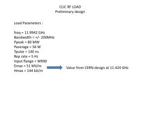
CLIC RF LOAD Preliminary design LoadParameters : freq = 11.9942 GHz Bandwidth = +/- 200MHz Ppeak = 80 MW Paverage = 56 W Tpulse = 140 ns Rep rate = 5 Hz Input flange = WR90 Emax = 51 MV/m Hmax = 144 kA/m Value from CERN design at 11.424 GHz
CERN design Freq = 11.424 GHz 8.05mm 16.1mm 30mm
CEA proposal : use of rectangularwaveguide for easiermachining WithStainlessSteel 430, sigma = 1.1 E6, mur = 6 a = 12.7 mm b = 10.16 mm PRF = 40 MW Emax = 51.1 MV/m Hmax = 134 MV/m Att = -16.5 dB/m a = 12.7 mm b = 3.4 mm PRF = 13.33MW Emax = 51.1 MV/m Hmax = 134 MV/m Att = -29.4 dB/m L(-3dB)=102 mm a = 12.75 mm b = 3.45 mm PRF = 13.33MW Emax = 48 MV/m Hmax = 125 MV/m Att = -26.1 dB/m L(-3dB)=116 mm a = 12.7 mm b = 1.7 mm PRF = 6.67 MW Emax = 51.1 MV/m Hmax = 134 MV/m Att = -48.8 dB/m L(-20dB)=410 mm a = 12.75 mm b = 1.75 mm PRF = 6.67 MW Emax = 47.7 MV/m Hmax = 124 MV/m Att = -42.7 dB/m L(-20dB)=468 mm
CEA proposal : easiermachining ? Top view 12.7mm 86.2mm 22.86mm 600mm
Stepheightreductionsparameters b1 = 10.16 mm b2 = 3.4 mm bstep = 5.86 mm Lstep = 35.53 mm R1 = 1mm R2 = 1mm a1 = 10.0 mm a2 = 8.0 mm for PRF = 13.33 MW (80 MW / 6) Emax = 52.2MV/m Hmax = 136.3 kA/m Lstep a1 a2 R1 R2 b1 bstep b2 b1 = 3.4 mm b2 = 1.7 mm bstep = 2.40 mm Lstep = 35.53 mm R1 = 0.2mm R2 = 0.2mm a1 = 5.0 mm a2 = 3.0 mm for PRF = 6.67 MW Emax = 52.6MV/m Hmax = 137.3 kA/m