Download
1 / 26
260 likes | 402 Views
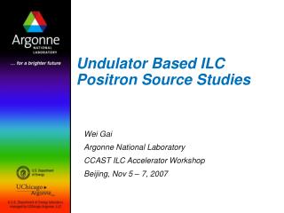
Current standing of the undulator based ILC positron source. Wei Gai AWLC 14 FNAL, May 13 2014. ILC TDR positron source location. Target for e+ production. 147 m helical undulator for photon production. Optical Matching Device for e+ capture. PBSTR 400MeV-5GeV. PPA (125-400MeV).

E N D
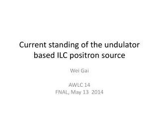
Current standing of the undulator based ILC positron source Wei Gai AWLC 14 FNAL, May 13 2014
ILC TDR positron source location Target for e+ production 147 m helical undulator for photon production Optical Matching Device for e+ capture PBSTR 400MeV-5GeV PPA (125-400MeV) Photon collimator for pol. upgrade PCAP Damping ring g Main e- beam from electron main linac gdump PLTR: Energy compression and spin rotation PTAPA (~125MeV) e- dump Main e- beam to IP 150 GeV beam to dump 2
Beamline Lattice • New lattice design has been done to comply with the new layouts as follow.
Outline • Undulator • Photon Collimator • Spinning Wheel Target • Material(TargetCollimator) Test • Flux concentrator • 300Hz truly conventional Source
Target system • The positron-production target is a rotating wheel made of titanium alloy (Ti6Al4V). • The diameter of the wheel is 1m and the thickness is 0.4 radiation lengths (1.4 cm). • During operation the outer edge of the rim moves at 100 m/s.
Positron Source Spinning Wheel Target • Prototype has been built and tested for eddy current issue. • Vacuum seal test of supporting shaft was not very successful. The current prototype is not robust enough for production system. • Still need to demonstrate full wheel with cooling channel. • Not funded for further test and demonstration.
Major Concerns on positron sources • Issues on moving forward on the current LLNL test. • Approaches are still viable? • Funding • Technical support • Alternative target design for undulator sources • Differential pumping, • Other type of targets? • Alternative scheme: • 300 Hz • How to do a technical design? • Resources on the technical design?
Existing (unsolved) Issues for Undulator based source • Beam dynamics, (OK) • Undulator (OK? Or @95%) • Target (heating and shocks) • Good? No issues? No critical problems (97%), there is rooms for further improvements. • Target support vacuum chamber, test at LLNL. • Life time of the vacuum seal (short time survival, but long term > a few weeks with vacuum spikes, no clear path forward at this point), no radiation damaging testing yet. , and • Cooling water impact on wheel dynamics (simulation should be done). • Rotating Seal leak tests at KEK planned. • New ideas: Non-contact (differenetial pumping), support, radiation cooling. Many others (later in the talk). • OMD, (OK) • Accelerator (NC) • SLAC test showed 14 MV/m. • Interfacing with damping ring (OK)
Conventional Source (300 Hz) • 6 GeV drive beam generation (OK? We have a design that will work Sband) • Target: Shocks, stresses, cooling (use SLC solution), slow rotating target wheel in vacuum, or pendulum, easier to seal). Need some engineering studies, require 5 m/s. • AMD, easy, existing (higher field next year, no issues at this point). • Beam capturing Linac • 300 Hz linac (hybrid L and S?) • Un-even beam loading, and energy compensation, RF gymnastics (solution exists, although may not be optimized). • Interface between L-band and S-band (bunch compressor?) A detailed beam dynamics simulation is required. • Costing according to ILC methodology. • Interface with damping ring simulation. • to be done.
Undulator • 4-m module fabricated and cryogenic tests were done at RAL • 4-m module magnets has been done at RAL • Shorter period with higher field helical undulator is desired to for luminocity at lower Ecm. • No one is known to be working on the developing of shorter period helical undulator with higher field.
Photon collimator • Photon collimator is an important part for positron source polarization upgrade. • DESY has a preliminary design. • Detail engineering design and prototyping is needed while not funded
Alternative undulator based target studies Developing a self loading machine gun in vacuum
Concept illustration EM rail gun to launch target pieces • Conduction cooling via the bottom of target. • Inspection and replacing of damaged target can be easily done on along this path. • Path can be easily adjusted to increase the cooling time. Magnetic braking to brake the target piece Commercially available Linear motors to move target pieces
Parameter estimation of the Rail gun for launching target External permanent magnetic field will be applied to improve • With the following assumptions: • length of rail 100cm, target bullet 1.4cmx1.4cmx6cm and rail has same cross section of target bullet • 1T external magnetic field and copper rail • We estimated that: • The current required to accelerate the target from 0 to 50m/s is about 4.5kAmps • The average heating power of gun is about 700W
Braking for target bullet • We have multiple options in slowing down the target bullet • Eddy current only braking • Magnetic braking with external power source • Magnetic braking without external power source • All of the above options are good candidate We can pick any one and then do the designing
Cooling/Inspection of the target bullet • Radiative/conduction cooling, • 60 seconds cooling time. Accurate calculation of the cooling time requires numerical simulation due to the non-uniform energy deposition in target bullet. • Guestimate: • We can over estimate it by assuming that the bullet got heated up 200oC above room temperature uniformly. In such exaggerated case, the cooling time required to cool it back down to 25oC using 10oC cooling agent outside on bottom of the recycling line can be estimated as about 46 seconds. • We have plenty of time to cool the bullet down. • Inspection and replacing damaged bullet can be easily adapted in the recycling line.
Transferring of target bullet • Transferring of target bullet is done via actuators driven by linear motors. • Taking the worst case scenario, friction coefficient of 0.9 for rubbing contact of untreated surface without lubricant, it needs 38N to overcome the friction. The works need to be done will be less than 0.52J per movement, or about 2.5W of power. • The loading actuator raise the weight of about 50 target pieces, 28N, by 1.4cm each time. The works need to be done will be about 0.39J per movement, or 2W of power. • Transferring the bullets inside the system should be quite easy.
Comments/Summary • We only had a few tests at LLNL, there are many improvements can be made. • If all the motors and mechanical parts can be placedin a rough vacuum, a good differential pumping can be achieved. • Alternative targets (not the scheme), can also be studied and tested.
Future Plan (or recommendations) • Undulator sources: • More conclusive test at LLNL (but require large fund). • Start looking at alternative schemes (bullet/differential-pumping/LiW/???), need to converge fast (in a year or less). • Undulator test, alignment and field uniformity. • Conventional source: • Many technical aspect of the conventional source need to be studied, system tests are also needed. • Layout should be done in six months. • It is challenging, but working with good engineering team ($$$$), I am optimistic.