Download
1 / 40
400 likes | 603 Views
Ore-inspiring structures - some numerical modelling perspectives on orogenic architectures favourable for formation and preservation of mineral deposits. Peter Sorjonen-Ward, Paul Gow 1 , Phaedra Upton 2 Yanhua Zhang CSIRO Exploration and Mining www.dem.csiro.au

E N D
Ore-inspiring structures- some numerical modelling perspectives on orogenic architectures favourable for formation and preservation of mineral deposits Peter Sorjonen-Ward, Paul Gow1, Phaedra Upton2 Yanhua Zhang CSIRO Exploration and Mining www.dem.csiro.au Current addresses 1pagow@mim.com.au 2 phaedra.upton@stonebow.otago.ac.nz
Purpose of presentation • Consider orogenic architecture that favours both formation and preservation of deposits • Review concept through coupled numerical models of deformation and flow based on • Archean Yilgarn craton • Modern PNG collisional zone • Smaller scale aspects not discussed here!
Or do they change with scale like this? Butterflies by M C Escher, 1950
Requirements for the formation and preservation of ore deposits • Critical architectures that efficiently transport and focus mineralizing fluids • Faults as episodic channels or seals – feedback between • strain softening or hardening • rupture, dilation and precipitation of minerals • Pervasive versus partitioned flow and access to rock • Geodynamic settings that favour preservation of deposits • Porphyry and epithermal systems dominant in young mountainous terrain • Late-orogenic lode gold deposits in greenschist facies and higher grade terrain, from Archean to Cainozoic
Generating sufficient fluids in the right place at the right time “structural control of ore deposits only takes place on faults that were active at the time that the hydrothermal system was active” Mike Etheridge, 2000 Hence, active coupling between fluids and deformation • In some terrains where architecture is potentially favourable, fluid production is ill-timed with respect to thermal peak • In some terrains, architecture is inappropriate – faults do not form connected network for accessing fluids • In some terrains, fluid supply is the limiting factor networks Additional paradox of high fluid flux with relatively low strain
Generating sufficient fluids in the right place at the right time What processes and sources generate an adequate fluid supply? • Granulitic lower crust inappropriate since already dehydrated • Fluids exsolved during crystallization of volatile-rich granites • Local metamorphic devolatilization • Rapidly formed accretionary prism could provide a more steady supply of fluid, but in many cases mineralization is late • Orogenically derived meteoric fluids if downdraw is feasible • Basinal fluids in submergent foreland basin or extending arc terrain – if salinity of mineralizing fluids is consistent • Mantle degassing – does permeability structure of lower crust permit sufficient fluid transfer?
Modelling orogenic architecrture • Thermomechanical modelling at orogenic scale well advanced • FLAC3D coupling of deformation and fluid flow • Darcy fluid flow in porous rock • Mohr-Coulomb elastic-plastic rheology • Feedback between fluid pressure and rock failure • No temperature dependance • No time dependance
Mechanisms for enabling fluid flow through low permeability environments Lithostatically overpressured system – requires sustained fluid supply
Critical orogenic architecture for generating ideal depositional sites • Dilational jogs in strike-slip systems are commonly invoked, based on earthquake research • Regional analysis often suggests this, but detailed studies often show more complex features • Importance of thrust-related subhorizontal systems • Yilgarn, PNG, central Asia (Muruntau) • Interaction between thrusts and reactivated transfer structures also considered important • Need to compromise between flow network that maximizes fluid-rock or fluid-fluid interaction, without resulting in dispersion rather than focussed deposition
Regional impressionLeft-stepping sinistral dilational jogLocal environmentBack rotation within contractional oblique-slip duplex Pampalo deposit, Finland
Deposits in hanging-wall of thrust systems:Porphyry Cu/Au deposits in PNG fold belt Ok Tedi Deposit (cross-section) from Mason (1994) Grasberg Deposit (plan view) from Widodo et al.,1999 From Mason (1994)
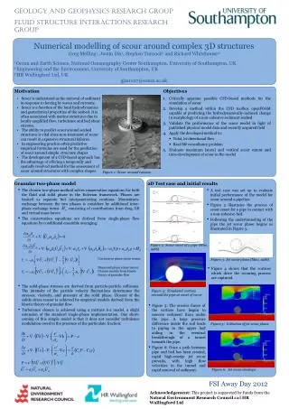
Fluid flow in thrust terrain controlled by hydraulic head, deformation and permeability Homogeneous permeability Highly permeable thrust High permeability in basal thrust and footwall stratigraphy Fluid sources related to melting and metamorphism
Some regional numerical models relating to mineralization during convergence • Interaction between thrusts and oblique convergence in PNG • Correlation between mineralization, uplift rate and reactivation potential of transfer faults • Divergent compressive structures in Yilgarn • Promoting lateral fluid flow and variable uplift to maximize potential for thermal and pressure gradients and mixing of diverse fluids
PNG FLAC3D model geometry • Architectural elements • Terranes of different strength • Contrast in platform strength • Arc-normal inherited transfer faults • Shelf-edge extensional fault • Dynamic Elements • Oblique sinistral collision • Convergence angle at15º and 45º • 1-2% shortening
Modelling volumetric strain Collision Obliquity: 45° - Greater volumetric strain at higher collision angles - associated with vertical extension - most pronounced where weak structures cut fold belt Collision Obliquity: 15°
Crustal uplift rates in PNG collision zone Effect of varying strength of crustal units and transfer faults Contours of vertical displacement dark = higher values
Modelling vertical displacement Current day topography Reactivated extensional structure adds peak Greater uplift against strong Australian crust
Incipient development of “pop-up” in uplifted region Fold belt Indentor
Transfer of deformation within orogen from thrust wedge to interior Thrusting velocities Incrementalshear strain low Potential backthrust formation where shear strain is localizing high
Some regional numerical models relating to mineralization during convergence • Interaction between thrusts and oblique convergence in PNG • Correlation between mineralization, uplift rate and reactivation potential of transfer faults • Divergent compressive structures in Yilgarn • Promoting lateral fluid flow and variable uplift to maximize potential for thermal and pressure gradients and mixing of diverse fluids
Yilgarn structural domains Eastern Goldfields Province Southern Cross Province
Tectonic wedging architecture • Allows uplift with preservation of seal • Lateral variations in thermal structure • Lateral fluid flow • Role of footwall rheology
FLAC3D model of Yilgarn section Why topographic elevation in the west? • Pressures greater in west, not merely higher temperatures • Envisage that system is about to collapse, removing relief and exhuming higher grade rocks by extensional shear along east-dipping Kunanalling and Ida faults • Alternative modified model with no topography
Fluid focussing in tectonic wedges Bardoc shear not dilating at depth
Fluid source beneath “Kalgoorlie region”- Bardoc shear still not active conduit
Hydrostatic pressure gradient – thermal effect of pluton locationBlue = anticlockwise flow, red = clockwise flow
Yilgarn 2D FIDAP thermal convective chemical model Dissolution regions (red) Precipitation of Au (blue) Maximum precipitation rate: 10.6 ppm per million years Geometry and permeability structures control temperature distributions and fluid mixing which in turn control the locations of gold precipitation
Yilgarn numerical models- principal conclusions”on tectonic wedging • Indicate generic structural sites that are favourable for fluid mixing and gold precipitation • footwall environments related to major shear zones, such as the Bardoc Shear • at rheological boundaries within broad antiforms such as the Scotia-Kanowna and Goongarrie–Mount Pleasant Antiforms
General implications of tectonic wedging architecture • Potential to create fault-bounded domains of differential uplift and overpressuring beneath relatively impermeable units • Generates opportunities for mixing of separate fluids or destabilization through rapid changes in pressure and temperature • May also contribute to the formation and preservation of greenschist facies deposits, in contrast to the lower long term preservation potential for deposits formed in elevated foreland fold and thrust belts.
General implications and speculation • Reinforces the dynamic feedback between deformation, magmatism and fluid production and migration • Requires that magmatic and metamorphic fluid generation is precisely timed with respect to deformation • Alternative fluid – and possibly heat - sources required if lower crust is already anhydrous • Importance of post-collisional subsidence and waning volcanism • Skellefte district, Sweden • Tasmanian Cambrian • Yilgarn • Need to study orogenic systems to identify wedging architectures, potentially through • Early deformation and polarity reversal • Facies changes recording subsidence during compression
Implications for (future) PNG mineralization • What will prevent loss of deposits formed at high crustal levels in areas of rapid uplift? • Could deposits also be forming at depth equivalent to greenschist or amphibolite facies? • If this is the case, then would greenschist facies gold deposits be exhumed within sinistral strike-slip systems orthogonal to recent granite-related transfer trend? • Changes in convergence vector expressed as • variations in uplift rate and hence lateral variations in metamorphic grade • systematic changes in simple shear kinematic component in deeper, orogen-parallel ductile shear zones
Incrementalshear strain Potential backthrust formation where shear strain is localizing Future shear zone-hosted gold deposits to be exhumed asPNG fold belt is translated westwards? low high
Orogenic processes, mineralization and preservation potential • Rifting and subsidence of arc maybe critical • PNG deposits related to rapid uplift of elevated terrain during ongoing plate convergence driven uplift of elevated terrain • Tectonic wedging • Provides potential for seal and lateral gradients in fluid pressure and supply • Potential for preservation compared to mineral systems formed in elevated terrain, if isostatic and thermal history appropriate • Local extensional domains but essentially compressive yet with decompression
Unfavourable orogenic architectures? • Orthogonal collision with aborted subduction of buoyant cratonic foreland • Rapid isostatic response and limited magmatism • Examples include: • Helvetic – Penninic nappes in Alpine system • Caledonian in Norway • 1.93-1.90 Ga stage of Svecofennian Orogeny • “Steady-state” orthogonal subduction beneath continental margin • Examples include: • Cretaceous Shimanto accretionary complex, despite sediment supply and postulated ridge subduction as anomalous thermal source
Effect of pluton location on fluid flow patternsBlue = anticlockwise flow, red = clockwise flow Pluton P3 Pluton P1 Pluton P4 Pluton P2