Download
1 / 26
260 likes | 373 Views
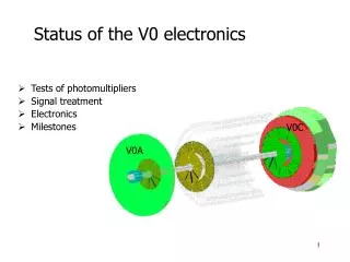
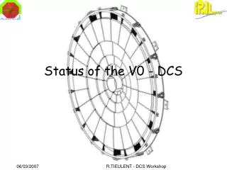
Status of the V0 - DCS. scintillator. connector. WLS fibres. V0C. PM. optical fibres. V0A. V0C. The V0 detector. Two scintillator hodoscopes at low angles trigger for the central detectors background filter for Muon 2 x 32 channels (V0A et V0C)

E N D
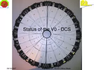
Status of the V0 - DCS R.TIEULENT - DCS Workshop
scintillator connector WLS fibres V0C PM optical fibres V0A V0C The V0 detector • Two scintillator hodoscopes at low angles • trigger for the central detectors • background filter for Muon • 2 x 32 channels (V0A et V0C) • 8 sectors of 4 channels per hodoscope R.TIEULENT - DCS Workshop
Installation and Commissioning Status • Key dates: • Detector installation in UX: 27-29 March • Accessible for DCS: HV + LV immediate after installation and FEE after cabling up early May. • Test in lab with DCS, DAQ, TRG: planned for week of April 16th • Test at P2: • First detector tests straight after installation (end March), using final HV but custom FEE. • Further commissioning with final electronics in May. R.TIEULENT - DCS Workshop
V0 ½ 1 16 64 1 25/04/05 [FSM?] Database(s) PVSS II PVSS II PVSS II Control room (ACR) OPCclient DIMclient User interface Ethernet CR3 CR3 PVSS II PVSS II OPC client OPC client Wiener OPCserver CAEN OPCserver E PCI-CAN Counting room C CR4-Z04 LV (+- 6V) SY1527 ACC Sharedwith T0 HV Cavern UX-O20 VME(wiener?) Detector(shoe box) PMT Inside magnet Detector High Voltage Low Voltage Crate Control
HV SEC1 HV SEC0 Ring 3 Ring 2 Ring 1 HV Ring 0 [0 – 3] The V0-FSM Tree V00_DET V00_FEE V0A V0C V00_INFR CAEN Crate VME Crate QUAD2 QUAD1 CIUs DCS board QUAD0 QUAD0 VME Crate [0 – 3] CAEN Crate CIU1 CIU2 CIU3 CIU4 CIU5 CIU6 CIU7 LV POS LV NEG CIU7 V0DCSBoard [0 – 7] [0 – 1] V0CIUBoard Control Unit Logical Unit Device Unit HV Channel LV- Channel LV+ Channel Device R.TIEULENT - DCS Workshop
HV SEC1 HV SEC0 Ring 3 Ring 2 Ring 1 HV Ring 0 [0 – 3] HV/LV Sub-system • Use the principle of Caen Channel Stock Settings developed by Antonio Franco for the HMPID. Will move to new FW component as soon as it becomes available. QUAD0 LV POS LV NEG [0 – 1] HV Channel LV- Channel LV+ Channel R.TIEULENT - DCS Workshop
QUADRANT HV_SECTOR 1 HV_SECTOR 0 LV Channel i=[0,3] LV Channel i=[0,1] Voltage Quadrant FSM R.TIEULENT - DCS Workshop
POWER_MODULE HV_SECTOR 1 HV_SECTOR 0 LV Channel i=[0,3] LV Channel i=[0,1] Voltage Quadrant Interlock If (Any LvChannel != ON) and (Any Hv Sector !=OFF) Then SWITCH_OFF HVSectors R.TIEULENT - DCS Workshop
Development of the control R.TIEULENT - DCS Workshop
The common V0/T0 CAEN Crate 1 2 3 4 5 6 7 8 9 10 11 12 13 14 15 16 HV A1733P HV A1733P HV A1733P HV A1733P HV A1733P HV A1733P LV A1513B LV A1513B LV A1513B LV A1513B HV A1733N HV A1733N LV A1513B LV A1513B V0 T0 CAEN Main frame + HV boards have been received last month. LV boards received last week. Tests on going in Lyon. R.TIEULENT - DCS Workshop
Résumé of HV/LV Sub-system • Crate Control: • The CAEN Crate delivered last month. Test of the system on going. • Have to develop the operation of the crate by 2 operators (T0/V0) • PVSS: • All panels developed • FSM: • FSM completed including the SW interlock between LV and HV. • CDB: • Configured and working for HV/LV sub-system • Cables: • HV cables are installed with connectors mounted on the C-Side • LV cables are installed (no connector yet) R.TIEULENT - DCS Workshop
Front End Electronics CCIU, pilot board - collects the CIU data - provides the final triggers - interface with the DAQ - interface with DCS • CIU, one board per ring • charge integration • time digitalization • trigger pre-processing DCS board SIU Mezzanine R.TIEULENT - DCS Workshop
PVSS II (FED - Client) FED Server InterComLayer FEE Client Front-End-Electronics in DCSControl and monitor channels Supervisory Layer Load configuration data from fileOR database Config. File Control Layer Config. DB Fee Server Field Layer DCS board CCIU CIU1 CIU1 CIU1 CIU1 CIU1 CIU1 CIU1 CIU8 R.TIEULENT - DCS Workshop
V0 Front-End-Electronics in DCSProgress Status • FEE server on DCS Board : • Driver for communication with CCIU : developed, tested and fully functional • FEE server : developed, tested, stable and fully functional • DIM server for CTP (to set CTP option code : developed, tested, stable and fully functional • Intercom PC(do we really need it ?) • FED server : In progress • FEE Client in progress • DIM test client for CTP fully functional • PVSS : upgraded from 3.1 to 3.6 (with some problems) • State machines defines and partially implemented • Front panels : in progress • DIM communication : in progress Will be ready mid-march R.TIEULENT - DCS Workshop
V0 Node State Diagram V00_DET V0A V0C FEE INFR R.TIEULENT - DCS Workshop
V0 Node Synchronization table R.TIEULENT - DCS Workshop
FSM Status HV/LV:Complete FEE:Work in progress, will be ready mid-March CAEN Crate: Need to implement the share control of the crate with T0 VME Crate: VME Crate is in Lyon. Start the development of control. Detector DCS FSM: Prototype exist. Final version ready end-March R.TIEULENT - DCS Workshop
Backup R.TIEULENT - DCS Workshop
Working principle • Control of the DCS board components : • TTCRx registers (example : TTC channel B data output for the CCIU board) • Control of the FEE boards (CCIU and CIU) components • HPTDCs • Modes • Pedestals • … • Collection and publication of monitoring data • DCS board • FEE R.TIEULENT - DCS Workshop
Control panels proposal • Main panel with : • Configure (from configuration file or database configuration parameters?) • Reset • Child panel with status of the different components of the system controlled by the DCS board • HPTDC on DCS board • CCIU registers • CIU registers • Sub-child panels with individual access to registers and functions of the previous components R.TIEULENT - DCS Workshop
Summary of calibration procedure Gains and pedestals computed by Online Monitoring using dedicated data (minimum bias and +/- 10 around the event of interest mini-events respectively)stored in the FEE and sent to the DAQ with theevents of interest. Note that this procedure is achieved by the FEE independently of theCentral Trigger Processor. These values will be written in the Calibration Data Base for later use by offliners and updated at each run change. Validity period will be run interval unless a hardware failure occurs. R.TIEULENT - DCS Workshop
FEE Use case 6 Data flow DAQ SHUTTLE DA F.R. Publish agent DAQ FES C.C. T0 custodial storage DAQ Logbook DB AliEn FC F.R. SHUTTLE Config’tion DB DCS F.R. : Filimon Roukoutakis C.C. C.C. : Christophe Combaret R.TIEULENT - DCS Workshop
Calibration excel file R.TIEULENT - DCS Workshop
Online output data for DAQ and monitoring • An event as seen by the V0 Front End Electronics will be: • Charges (64). • Arrival times (64) and time response widths (64). • Beam-Beam (BB) and Beam-Gas (BG) flags (64). • States of the 5 triggers sent to the CTP (MinBias, BB, BG, Central,SemiCentral). • For each event triggered by a L2 signal coming from the CTP (called Event-Of-Interest), the following information will be sent to the DAQ: • 1. The event of interest itself with all the parameters listed above, for physics analysis • 2. The events between EoI-10 to EoI+10 (charges and BB/BG flags), for monitoring pedestals, pile-up… • 3. The 10 last V0 Minimum Bias events (charges and BB/BG flags), for monitoring gains R.TIEULENT - DCS Workshop
Calibration procedure • Calibration parameters are computed online in the DAQ LDC from sampling dedicated data • Results are made available as ROOT files in the DAQ FES • DCS accesses the Root file in the DAQ FES, compares the parameter values to reference values stored in the DCS Configuration DB and updates the FEE values if needed. R.TIEULENT - DCS Workshop
Calibration Calibration CDB file has been created and CDB reading implemented. Calibration parameters stored into CDB are : • 128 gains, 128 pedestal means, 128 pedestal sigmas (2 QDC per channel) • 64 time gains and 64 time offsets i.e. 512 floats, 4 kB All these parameters are accessible through class AliVZEROCalibData R.TIEULENT - DCS Workshop