Download
1 / 19
610 likes | 1.73k Views
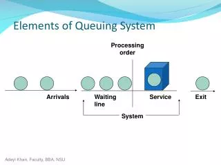
Elements of a Digital Communication System. Block diagram of a communication system:. Mathematical Models for Communication Channels. Additive Noise Channel: In presence of attenuation: . Mathematical Models for Communication Channels. The Linear filter channel:.

E N D
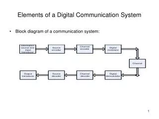
Elements of a Digital Communication System • Block diagram of a communication system:
Mathematical Models for Communication Channels • Additive Noise Channel: • In presence of attenuation:
Mathematical Models for Communication Channels • The Linear filter channel:
Mathematical Models for Communication Channels • Linear Time-Variant Filter Channel: • Are charachterized by a time-variant channel impulse response
Representation of Band-Pass Signals and Systems • Representation of Band-Pass Signals: Energy of the signal: • Representation of Linear Band-Pass Systems: • Response of a Band-Pass System to a Band-Pass Signal:
Orthogonal Expansion of Signals • We can express M orthonormal signals as a Linear combination of basis functions and hence can be defined as • Linear digitally modulated signals can be expanded in terms of two orthonormal basis functions given by: and
Representation of Digitally Modulated Signals • Pulse-amplitude-modulated Signals (PAM): • Phase-modulated signals (PSK): • Quadrature amplitude modulation (QAM): m=1,2,…M m=1,2,..,M,
Representation of Digitally Modulated Signals • Orthogonal multidimensional signals: • Biorthogonal signals: • Simplex signals: • m=1, 2,…, M.. • Signal waveforms from binary codes:
Optimum Receivers Corrupted by additive White Gaussian Noise- I • General Receiver: Receiver is subdivided into: • 1. Demodulator. • (a) Correlation Demodulator. • (b) Matched Filter Demodulator. • 2. Detector.
Optimum Receivers Corrupted by additive White Gaussian Noise- II • Correlation Demodulator: • Decomposes the received signal and noise into a series of linearly weighted orthonormal basis functions. • Equations for correlation demodulator:
Optimum Receivers Corrupted by additive White Gaussian Noise- III • Matched Filter Demodulator: • Equation of a matched filter: • Output of the matched filter is given by: k=1,2, …N
Optimum Receivers Corrupted by additive White Gaussian Noise- IV • Optimum Detector: • The optimum detector should make a decision on the transmitted signal in each signal interval based on the observed vector. • Optimum detector is defined by: m=1,2,… M or
OFDM • It is a block modulation scheme where data symbols are transmitted in parallel by employing a large number of orthogonal sub-carriers. • Equation of complex envelope of the OFDM signal: • where
General FFT based OFDM system-I • Block diagram of FFT based OFDM transmitter : • Equations at the transmmitter end:
General FFT based OFDM system-II • Block diagram of FFT based OFDM receiver: • At the demodulator:
General FFT based OFDM system-II • Merits of OFDM: • 1. the modulation and the demodulation can be achieved in the frequency-domain by using a DFT. • 2. the effects of ISI can be eliminatedwith the introduction of the guard interval.
IMPLEMENTATION OF OFDM SYSTEM-I • Basic implementation of OFDM system:
SIMULATION RESULTS. • Perfomance charachteristics were obtained for the simulated OFDM system.
Conclusion. • 1. OFDM communication system exhibits better Pe Vs SNR curves in case of Non-Fading channel as compared to the Fading channel. • 2. As the value of the SNR is increased the value of Pe gradually decreases. • 3. Perfomance charachteristics of simulated OFDM communication system are consistent with the performance charachteristics of the general OFDM communication system.