Download
1 / 46
670 likes | 1.43k Views
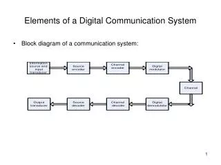
Lecture 7 Digital Communication System. Dr. Rashid Saleem. INTERSYMBOL INTERFERENCE (ISI). Intersymbol Interference Combatting ISI Nyquist’s First Method for zero ISI Raised Cosine- Rolloff Pulse Shape Nyquist Filter Eye Patterns ISI on Eye Patterns.

E N D
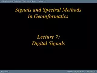
Lecture 7Digital Communication System Dr. Rashid Saleem
INTERSYMBOL INTERFERENCE (ISI) • Intersymbol Interference • Combatting ISI • Nyquist’s First Method for zero ISI • Raised Cosine-Rolloff Pulse Shape • Nyquist Filter • Eye Patterns • ISI on Eye Patterns
Intersymbol Interference (ISI) • In telecommunication, intersymbol interference (ISI) is a form of distortion of a signal in which one symbol interferes with subsequent symbols. • This is an unwanted phenomenon as the previous symbols have similar effect as noise, thus making the communication less reliable. • ISI is usually caused by multipath propagation orthe inherent non-linear frequency response of a channel causing successive symbols to "blur" together. • The presence of ISI in the system introduces errors in the decision device at the receiver output.
Intersymbol Interference (ISI) • Therefore, in the design of the transmitting and receiving filters, the objective is to minimize the effects of ISI, and thereby deliver the digital data to its destination with the smallest error rate possible. • Ways to fight intersymbol interference include: • adaptive equalization • error correcting codes
Intersymbol Interference (ISI) • Intersymbol interference (ISI) occurs when a pulse spreads out in such a way that it interferes with adjacent pulses at the sample instant. • Example: assume polar NRZ line code. The channel outputs are shown as spreaded (width Tb becomes 2Tb) pulses shown (Spreading due to bandlimited channel characteristics). Channel Output Pulse width Tb Channel Input Pulse width Tb Data 1 Data 0
0 1 1 1 1 0 0 1 1 1 1 0 Intersymbol Interference • For the input data stream: • The channel output is the superposition of each bit’s output: Resultant Channel Output Waveform
Intersymbol Interference • If the rectangular multilevel pulses are filtered improperly as they pass through a communications system, they will spread in time, and the pulse for each symbol may be smeared into adjacent time slots and cause Intersymbol Interference. • How can we restrict BW and at the same time not introduce ISI? 3 Techniques.
Intersymbol Interference • Flat-topped multilevel input signal having pulse shape h(t) and values ak: • he(t) is the pulse shape that will appear at the output of the receiver filter.
Intersymbol Interference • Equivalent Impulse Response he(t) : • Equivalent transfer function: • Receiving filter can be designed to produce a needed He(f)in terms of HT(f) and HC(f): • Output signal can be rewritten as: • He(f), chosen such to minimize ISI is called EQUALIZINGFILTER)
Intersymbol Interference HT(f) Hc(f) HR(f) Y(t) Trans filter Channel Receiver filter Y(tm) Ak The received Signal is the transmitted signal, convolved with the channel And added with AWGN (Neglecting HTx,HRx) ISI - Inter Symbol Interference
Combating ISI • Three strategies for eliminating ISI: • Use a line code that is absolutely bandlimited. • Would require Sinc pulse shape. • Can’t actually do this (but can approximate). • Use a line code that is zero during adjacent sample instants. • It’s okay for pulses to overlap somewhat, as long as there is no overlap at the sample instants. • Can come up with pulse shapes that don’t overlap during adjacent sample instants. • Raised-Cosine Rolloff pulse shaping • Use a filter at the receiver to “undo” the distortion introduced by the channel. • Equalizer.
Nyquist’s First Method for Zero ISI • It should be noted that it is sufficient to eliminate interference at decision making instants of every bit to get zero ISI • Thus, Nyquist achieved zero ISI by choosing a pulse shape that has a non-zero amplitude at its center (say t=0) and zero amplitudes at t = nTb, where Tbis the separation between successive transmitted pulses
Nyquist’s First Method for Zero ISI How does a sinc work? • A sinc pulse has periodic zero crossings. If successive bits are positioned correctly, there will be no ISI at sampling instants. No ISI Nadjacent pulses Go to zero hence no ISI Tb Sampling instants
Nyquist’s First Method for Zero ISI • ISI can be eliminated by using an equivalent transfer function, He(f), such that the impulse response satisfies the condition: Sampling Instants ISI occurs but, NO ISI is present at the sampling instants
Nyquist’s First Method for Zero ISI He(f) 1/fs fs/2 -fs/2 • There will be NO ISI and the bandwidth requirement will be minimum (Optimum Filtering) if the transmit and receive filters are designed so that the overall transfer function He(f) is: • This type of pulse will allow signalling at a baud rate of D=1/Ts=2B (for Binary R=1/Ts=2B) where B is the absolute bandwidth of the system.
Nyquist’s First Method for Zero ISI He(f) 1/fs Zero crossings at non-zero integer multiples of the bit period fs/2 -fs/2 he(t) • Since pulses are not possible to create due to: • Infinite time duration. • Sharp transition band in the frequency domain. • The Sinc pulse shape can cause significant ISI in the presence of timing errors. • If the received signal is not sampled at exactly the bit instant (Synchronization Errors), then ISI will occur. • We seek a pulse shape that: • Has a more gradual transition in the frequency domain. • Is more robust to timing errors. • Yet still satisfies Nyquist’s first method for zero ISI.
Raised Cosine-Rolloff Nyquist Filtering • The following graph shows the impulse or time domain response of a Nyquist filter. • We have seen this figure before. • Nyquist filters have the property that their impulse response rings at the symbol rate. • The filter is chosen to ring or have the impulse response of the filter cross through zero at the symbol clock frequency.
Raised Cosine-Rolloff Nyquist Filtering • The time response of the filter goes through zero with a period that exactly corresponds to the symbol spacing. • Adjacent symbols do not interfere with each other at the symbol times because the response equals zero at all symbol times except the center (desired) one. • Nyquist filters heavily filter the signal without blurring the symbols together at the symbol times. • This is important for transmitting information without errors caused by Inter-Symbol Interference. • Note that Inter-Symbol Interference does exist at all times except the symbol (decision) times.
Raised Cosine-Rolloff Nyquist Filtering • Usually the filter is split, half being in the transmit path and half in the receiver path. • In this case root Nyquist filters (commonly called root raised cosine) are used in each part, so that their combined response is that of a Nyquist filter. • Sometimes filtering is desired at both the transmitter and receiver. • Filtering in the transmitter reduces the adjacent channel-power radiation of the transmitter, and thus its potential for interfering with other transmitters. • Filtering at the receiver reduces the effects of broadband noise and also interference from other transmitters in nearby channels.
Raised Cosine-Rolloff Nyquist Filtering • To get zero Inter-Symbol Interference (ISI), both filters are designed until the combined result of the filters and the rest of the system is a full Nyquist filter. • Potential differences can cause problems in manufacturing because the transmitter and receiver are often manufactured by different companies. • The receiver may be a small hand-held model and the transmitter may be a large cellular base station. • If the design is done correctly, the results are the best data rate, the most efficient radio, and reduced effects of interference and noise. • This is why root-Nyquist filters are used in receivers and transmitters as √Nyquistx√Nyquist =Nyquist. • Matched filters are not used in Gaussian filtering.
Raised Cosine-Rolloff Nyquist Filtering • Because of the difficulties caused by the Sa type pulse shape, consider other pulse shapes which require more bandwidth such as the Raised Cosine-rolloff Nyquist filter but they are less affected by synchrfonization errors. • The Raised Cosine Nyquist filter is defined by its rollof factor number r=fΔ/fo.
Raised Cosine-Rolloff Nyquist Filtering • Now filtering requirements are relaxed because absolute bandwidth is increased. • Clock timing requirements are also relaxed. • The r=0 case corresponds to the previous Minimum bandwidth case.
Raised Cosine-Rolloff Nyquist Filtering • Impulse response is given by: • The tails of he(t) are now decreasing much faster than the Sa function (As a function of t2). • ISI due to synchronization errors will be much lower.
Raised Cosine-Rolloff Nyquist Filtering Frequency response and impulse responses of Raised Cosine pulses for various values of the roll off parameter.
Raised Cosine-Rolloff Nyquist Filtering • Illustrating the received bit stream of Raised Cosine pulse shaped transmission corresponding to the binary stream of 1 0 0 1 0 for 3 different values of r=0, 0.5, 1. 1 0 0 1 0 1 001 0
Bandwidth for Raised Cosine Nyquist Filtering • The bandwidth of a Raised-cosine (RC) rolloff pulse shape is a function of the bit rate and the rolloff factor: • Or solving for bit rate yields the expression: • This is the maximum transmitted bit rate when a RC-rolloff pulse shape with Rolloff factor r is transmitted over a baseband channel with bandwidth B.
Nyquist Filter • Raised Cosine Filter is also called a NYQUIST FILTER. • NYQUIST FILTERS refer to a general class of filters that satisfy the NYQUIST’s First Criterion. • Theorem: A filter is said to be a Nyquist filter if the effective transfer function is : • There will be no intersymbol interference at the system output if the symbol rate is
Eye Diagram The eye diagram is created by taking the time domain signal and overlapping the traces for a certain number of symbols. The open part of the signal represents the time that we can safely sample the signal with fidelity (accuracy & quality)
Vertical and Horizontal Eye Openings The vertical eye opening or noise margin is related to the SNR, and thus the BER A large eye opening corresponds to a low BER The horizontal eye opening relates the jitter and the sensitivity of the sampling instant to jitter The red brace indicates the range of sample instants with good eye opening At other sample instants, the eye opening is greatly reduced, as governed by the indicated slope
Distortion Noise Margin ISI on Eye Patterns • The amount of ISI can be seen on an oscilloscope using an Eye Diagramor Eyepattern. Amplitude Extension Beyond Tb is ISI Time (Tb)
Measuring Received Performance • A: time interval over which the waveform can be sampled • B : margin over noise • C : distortion of zero crossings • D : slope : sensitivity to timing error • E : Maximum distortion • t* : optimum sampling instant measured with respect to the time origin.
Interpretation of Eye Diagram 10 points in the final
Jitter in Circuit design Circuit design
Eye Diagram Setup Eye diagram is a retrace display of data waveform Data waveform is applied to input channel Scope is triggered by data clock Horizontal span is set to cover 2-3 symbol intervals Measurement of eye opening is performed to estimate BER BER is reduced because of additive interference and noise Sampling is also impacted by jitter
Eye Diagram Eye diagram is a means of evaluating the quality of a received “digital waveform” By quality is meant the ability to correctly recover symbols and timing The received signal could be examined at the input to a digital receiver or at some stage within the receiver before the decision stage Eye diagrams reveal the impact of ISI and noise Two major issues are 1) sample value variation, and 2) jitter and sensitivity of sampling instant Eye diagram reveals issues of both Eye diagram can also give an estimate of achievable BER
Figure 4.34 (a) Eye diagram for noiseless quaternary system. (b) Eye diagram for quaternary system with SNR 20 dB. (c) Eye diagram for quaternary system with SNR 10 dB. Eye diagram for 4-level (M=1)systems – Eye openings stacked vertically one upon the other EE 541/451 Fall 2007