Download
1 / 20
220 likes | 572 Views
The RCU2 ALICE TPC readout electronics consolidation for Run 2. Johan Alme Bergen University College, Norway on behalf of the ALICE-TPC collaboration TWEPP 2013, Perugia , Italy 23rd – 27th September 2013. ALICE detector. TPC detector. Present ALICE TPC Readout Electronics.

E N D
The RCU2 ALICE TPC readout electronics consolidation for Run 2 Johan Alme Bergen University College, Norway on behalf of the ALICE-TPC collaboration TWEPP 2013, Perugia, Italy 23rd – 27th September 2013
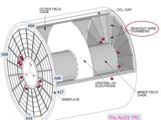
ALICE detector TPC detector Johan Alme - TWEPP 2013, Perugia, Italy 23rd – 27th September 2013
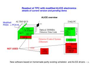
Present ALICE TPC Readout Electronics • TPC is dividedinto 2 x 18 Sectors: • 216 Readout Control Units (RCUs) • 4356 Front End Cards (FECs) • The RCU is a complex system: • RCU Motherboard • Detector Control System (DCS) Board • Embedded Linux platform • SourceInterfaceUnitCard (SIU) • In total 3 PCBswith 4 FPGAs • 2 branches per RCU of a multidropparallel bus • 18 – 25 FECs per RCU • dependingonposition • Peakbandwidth 200 MB/s Johan Alme - TWEPP 2013, Perugia, Italy 23rd – 27th September 2013
ALICE Run 2 Scenario • Run 2 is theperiodbetween Long Shutdown 1 (LS1) and Long Shutdown 2 (LS2) • Planned start of Run 2: January 2015 • Run 2 will have higherinteraction rates and highertrackdensities • Expectedvalues for Pb-Pbcollisions: • Peakluminocity: 1 – 4 x 1027 cm-2s-1 • 8 – 30 kHz interaction rate • Current ALICE design value: 8 kHz • 40% more data for centralevents • Eventsizesincrease from 65 MB to 90MB • Higher readout speed needed • Higherradiationload => more Single EventUpsets Lowmultiplicityevent from Run 1 Highmultiplicityevent is completelycrowded Run 2 will have evenhighermultiplicity Johan Alme - TWEPP 2013, Perugia, Italy 23rd – 27th September 2013
Motivation for Upgrade (I) • Data Rate Limitations: • Current bottleneck: Bandwidth of the data bus • ≤ 200 MB/s per branch • Large (fixed) overhead - addressing and header • Bandwidth of optical detector data link (DDL) • 160 MB/s • Stability Limitations (Run 1 experiences): • End-Of-Run situations caused by radiation related errors in the TPC electronics have been seen • DCS board failures frequent – few per fill • Not “mission critical” Two read-out modes: sparse and full read-out. Read-out time for full TPC is defined by the slowest read-out partition Johan Alme - TWEPP 2013, Perugia, Italy 23rd – 27th September 2013
Motivation for Upgrade (II) • Main message: • The readout performance is limited by the parallel bus architecture • This reduces the expected performance for Run 2 • Conclusion: We need a faster data readout than what the current solution provides! • Both main FPGAs on the RCU has a relatively high SEU susceptibility and almost no design-level protection • Not enough resources in the FPGAs to implement it • Conclusion: With even the higher luminosity in Run 2 we need an improved radiation tolerance for the readout chain! Johan Alme - TWEPP 2013, Perugia, Italy 23rd – 27th September 2013
RCU2The ALICE TPC Consolidation Effort • Constraints: • Time-budget • Reuse all exisitinginterfaces • TTC fiber • DAQ fiber • Ethernet cable • Power cable • GTL bus • No change to form-factor and cooling • Improveradiationtolerance • Increase data rate to meet Run2 conditions • Solution – RCU2: • One single radiation tolerant FLASH based SmartFusion2 FPGA • FPGA design composed of a few building blocks largely based on existing modules • Backplanes - Double the number of readout branches to 4 branches • Nice to have functionality: Radiation Monitor Johan Alme - TWEPP 2013, Perugia, Italy 23rd – 27th September 2013
Branch Partitioning • There are 6 readout partitions per TPC sector: • 6 different sizes of backplanes • Two wings per partition • Each wing is electrically split into two branches each with new branch naming convention • A A_inner (AI) | A_outer (AO) • B B_inner (BI) | B_outer (BO) • Depending on partition – various number of FECs per branch • RP0: 5 + 4 + 4 + 5 • RP1: 6 + 6 + 6 + 7 • RP2: 5 + 4 + 4 + 5 • RP3-RP5: 5 + 5 + 5 + 5 RP5 RP4 RP3 RP2 RP1 RP0 Johan Alme - TWEPP 2013, Perugia, Italy 23rd – 27th September 2013
RCU2 Backplanes • Two options: • Adapter cardsolution • All in One solution • Pros and Cons are considered for both options • Prototypes will be produced for both options and decision taken afterwards. • Location of connectors between RCU2 and branches are fixed: • Backward compatible with current backplanes Present backplanes Electricalsplitof backplanes Adapter cardsolution All in One solution Johan Alme - TWEPP 2013, Perugia, Italy 23rd – 27th September 2013
RCU2 Hardware Johan Alme - TWEPP 2013, Perugia, Italy 23rd – 27th September 2013
Microsemi Smartfusion2 • The Smartfusion2 M2S050-FG896 provides: • Radiation Tolerant Flash Cells • SECDED encoded DDR RAM interface • MicrocontrollerSubsystemwith ARM Cortex M3 and usefulperipherals • Platform for Embedded Linux • 5 Gb/s operation in custom working mode on one lane of the SERDESIF for DDL2* • Enough resources to have TMR on vital parts of the logic * Not availablebefore end of 2013 Johan Alme - TWEPP 2013, Perugia, Italy 23rd – 27th September 2013
RCU2 Hardware • Pictures shows first draft of RCU2 layout • Importantpoints: • Backwardcompatibleregardingplacementofconnectors • Reuseofcooling plates • Constraintsplacementregarding heat dissipation and connector locations • Power estimates • Typicalvalues (currentconsumption): • Ext 4V3: ~1.2A • Ext 3V3: ~4.3A • The GTL bus drivers areby far the most power-hungrycomponentsontheboard RCU2 front RCU2 back Johan Alme - TWEPP 2013, Perugia, Italy 23rd – 27th September 2013
RadMon – Radiation Monitor • On the present RCU there is an additional FPGA thatcounts and correctsSEUs in theconfigurationmemory in themain FPGA • This acts as a radiation monitor! • This is an interesting feature to keep for the RCU2: • Additional SRAM memory and Microsemi proASIC3 250 added to the RCU2 • Not enoughuser-IOsonthe smartFusion2 for this feature • Low risk – design alreadydone and proven* • Cypress SRAM – same as used for the latest LHC RadMondevices • Extensively characterized in various beams (n, p, mixed) and compared/benchmarked to FLUKA MC simulations * Arild Velure ”Anvendelse av FPGA som preprosessor i en SRAM-basert nøytrondetektor”, Master Thesis 2011 Johan Alme - TWEPP 2013, Perugia, Italy 23rd – 27th September 2013
TTC interface • TTC = Timing, Trigger and Control • System responsible for distributionof system clock and triggers • One ofthechallengesoftheupgrade is thattheTTCrx ASIC is outofstock • This is theTrigger/Clockreceiver chip for the Front end Electronics • No provenradiation tolerant TTCrxreplacementexist! • Solution: • HFBR 2316T OpticalReceiver (suggested by TTC group) • MAX3748 Post limitingamplifier • Clock Data Recoveryinternally in FPGA • Challenge: The clock signal must be recoveredwithhighaccuracy! • This has beentested and verified in the lab withreal-lifesetup • Radiationtolerance not yetproven • Involves simple componentswithnoconfiguration registers – Successverylikely! • Makes reuseofexisting FPGA modulesveryeasy Johan Alme - TWEPP 2013, Perugia, Italy 23rd – 27th September 2013
RCU2 FPGA design • The ARM Cortex M3 hosts an Embedded Linux platform • New drivers areneeded • Most software can be reused • The FPGA PLD design is heavilybasedonthe present RCU design with a fewnew features • New readout scheme: • Orderingofchannels by pads & rows • Higherclock speed • Pause and recoverimplementation • Discardof Junk data • Important: Improveradiationtolerance Johan Alme - TWEPP 2013, Perugia, Italy 23rd – 27th September 2013
Readout Scheme and Data Ordering (I) • One rowof sensor padsarespread over all 4 branches • Data pre-prossesingdemandsthat data is shipedordered by padrow • Needed to findchargeclustersalongtracks in the HLT/DAQ system • A chunkof data is defined: • Numberofchannelsbelonging to same padrow and branchordered by pad location • The order ofthechannelswithin a chunk is configurable to match pad location Johan Alme - TWEPP 2013, Perugia, Italy 23rd – 27th September 2013
Readout Scheme and Data Ordering (II) • Given averageeventsizeestimations for 0-10% centralevents (Run 2): • Max averagesizeofonechunk is ~35 kBit • Readout partition 1 • Highestchanneldensity • Largest data volume • Bandwidth per branch: ~1.0 Gbit/s • Min. Readout speed per FIFO: 32 bit @ 125 MHz • Bandwidth RCU2 DDL2 interface: 4.0 Gbit/s • Given internalmemoryresources: • Branch FIFO capacity: 4.7 averagemaxsizechunks • Simulationsareplanned to getexactfigures Johan Alme - TWEPP 2013, Perugia, Italy 23rd – 27th September 2013
IrradiationCampaigns • Component testing will be done at Oslo Cyclotron (in-house) • ~30 MeV protons • 1 slot in October & 3 slots in November • Wecan not test all componentsindividually (No time!) • A list have beenmadewithcomponentswefind it critical to test as early as possible • This is essentially ”new” componentsthatwedon’t have experiencewith, or • Components in critical parts ofthe design (i.e. TTC chain) • Testing ofthe smartFusion2 • Effectsof Single Event Transients can be a problem at higherclock speeds* • RCU2 system test in Uppsala or PSI earlynextyear • 180 MeV Protons & Neutronspossible • Beamtime will be requestedwhenwearecertain to reachthemilestone * https://indico.cern.ch/getFile.py/access?resId=0&materialId=slides&confId=152527 Johan Alme - TWEPP 2013, Perugia, Italy 23rd – 27th September 2013
Summary & Outlook • The proposed upgrade would enable ALICE to collect a significant larger amount of events in the central barrel at a moderate cost • Estimated cost: ~455 kCHF • The read-out time for TPC events is estimated to be improved by a factor of up to 2.6 • TPC will conform to the running scenario envisaged for Run 2 of ALICE • SystemC simulations are planned to confirm this figure • Radiation tolerance will be improved • Biggest challenge for the project is the tight time-budget constraint • At time of writing we are approximately on schedule Johan Alme - TWEPP 2013, Perugia, Italy 23rd – 27th September 2013
Thanks for Listening • RCU2 people(in noparticular order): Johan Alme (johan.alme@hib.no) – Bergen University College, Norway Lars Bratrud, Jørgen Lien, Rune Langøy – Vestfold University College, Norway Ketil Røed, Chengxin Zhao – University of Oslo, Norway Kjetil Ullaland, Dieter Röhrich, Shiming Yang, Arild Velure, Inge Nikolai Torsvik, Christian Torgersen – University of Bergen, Norway Attiq Ur Rehman – COMSATS, Islamabad, Pakistan Tivadar Kiss, Ernö David – Cerntech, Budapest, Hungary Christian Lippman– GSI Darmstadt, Germany Anders Oskarsson, Peter Christiansen, Lennart Osterman – University of Lund, Sweded Harald Appelshäuser, Torsten Alt , Attilio Tarantola – Goethe University Frankfurt, Germany Fillipo Costa – CERN, Switzerland Taku Gunji – University of Tokyo, Japan Johan Alme - TWEPP 2013, Perugia, Italy 23rd – 27th September 2013