The ALICE TPC Team
610 likes | 843 Views
The ALICE TPC Team. Project leader: Peter Braun-Munzinger, GSI Darmstadt Deputy project leader: Johanna Stachel, Heidelberg Technical coordinator: Peter Gl ä ssel, Heidelberg. Bergen D. R ö hrich D ata acquisition Bratislava B. Sitar 1/2 IROC series production

The ALICE TPC Team
E N D
Presentation Transcript
The ALICE TPC Team Project leader: Peter Braun-Munzinger, GSI Darmstadt Deputy project leader: Johanna Stachel, Heidelberg Technical coordinator: Peter Glässel, Heidelberg BergenD. Röhrich Data acquisition BratislavaB. Sitar 1/2 IROC series production CERN T. Meyer Field cage CERN L. Musa Electronics CopenhagenB.S. Nielsen Laser system KrakowM. Kowalski Simulations Darmstadt GSI H.R. Schmidt ROC engineering, prototyping, series production,simulations Darmstadt TU H. Oeschler Electronics testing Frankfurt R. Renfordt Electronics testing,installation Heidelberg KIP V. Lindenstruth Data acquisition, HLT Heidelberg PIJ. Stachel Electronics, engineering, IROCproduction,OROC production Lund H.A. Gustafsson Electronics ALICE TPC, Schleching 2003
Overview Field Cage Readout chambers Laser system Cooling system Gas system Readout electronics Performances Outlook Outline ALICE TPC, Schleching 2003
The ALICE Detector at LHC ALICE TPC, Schleching 2003
5.5 TeV CM-energy (NN) Pb + Pb (and probably lighter ions) rapidity density worst case dN/dy = 8000 8 kHz inelastic collision rate rapidity interval 17 units 25 ns bunch spacing General Conditions at LHC for Heavy Ion Collisions ALICE TPC, Schleching 2003
Central event Central event Pb-Pb • dN/dy = 8000 • only a 2 deg slice! ALICE TPC, Schleching 2003
Summary of TPC Specs • || < 0.9 (full length tracks) • 845 < r < 2466 mm • drift length 2 x 2.5 m, 100 kV, 88 s drift • Ne/CO2 (90/10) • 18 x 2 sectors with 2 ROC’s • 557 568 channels, 512 10 bit time samples (5.7 MHz) • event size 60 MB • occupancy 40 to 15% @ dN/dy = 8000 • position resolution 800 to 1250 m in r and z • material budget 3.5 to 5% X0 ALICE TPC, Schleching 2003
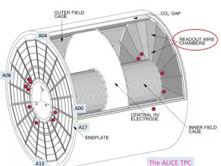
TPC Field Cage Overview • Inner and outer Isolation vessels • Aluminum End Plates housing ROC’s • Field defining system: strips supported by rods ALICE TPC, Schleching 2003
Field Cage parts 5560 5000 Isolation volume End wheel Drift volume Isolation volume ALICE TPC, Schleching 2003
Inner Field Cage Production Cylinders are fabricated from segments glued together (lashing). ALICE TPC, Schleching 2003
Inner Field Cage Vessel: Assembly ALICE TPC, Schleching 2003
Inner Field Cage Vessel: Guard Rings 100 mm Potential guard rings glued to inner and outer surface of Inner Field Cage Vessel ALICE TPC, Schleching 2003
Field Cage Assembly ALICE TPC, Schleching 2003
Checking the End Wheel ALICE TPC, Schleching 2003
Leak test of inner vessel ALICE TPC, Schleching 2003
Flange of Outer Isolation Volume Forged and machined rings from André Constructions Mécaniques - Grenoble ALICE TPC, Schleching 2003
Single mylar foil 3 sheets glued Carbon fiber frame proven technique (NA48) Field Cage: Central Electrode ALICE TPC, Schleching 2003
Central Electrode: Prototype 25 µm aluminized Mylar on Al frame of 10 cm width, Ø approximately 3 m. ALICE TPC, Schleching 2003
Service Support Wheel • Carries front end electronics and services ALICE TPC, Schleching 2003
Service Support Wheel Model • 3 sectors SSW • 1 sector end plate • Train all operations ALICE TPC, Schleching 2003
Readout Chambers • 18 sectors each side, 2 chambers/sector • MWPC’s, 557568 cathode pads • gas gain 2x10⁴ • gated • pad sizes 4x7.5, 6x10, 6x15 mm2 • pad occupancy 15 … 40% (dN/dy = 8000) • 5.7 MHz 10 bit ADC sampling, 512 samples • position resolution 800 … 1250 m (r, z) ALICE TPC, Schleching 2003
Readout Chamber Wire Geometry cathodes gate wires anodes pads ALICE TPC, Schleching 2003
Pad Plane • optimized pad sizes • 4 x 7.5 mm • 6 x 10 mm • 6 x 15 mm • segmented: IROC and OROC • total 557 568 pads ALICE TPC, Schleching 2003
IROC Module Tests HV 1260 … 1310 V @ gas gain 20,000 ALICE TPC, Schleching 2003
IROC Gain Homogeneity (Drop at ends due to 55Fe source geometry) ALICE TPC, Schleching 2003
Leak Test ALICE TPC, Schleching 2003
Adjusting Wires vs Pads ALICE TPC, Schleching 2003
IROC Detail Photos FEE side with one cable Pad side before adding anode wire plane ALICE TPC, Schleching 2003
IROC Connected to Front End Card FEC in Cu sandwich 6 cables per FEC ALICE TPC, Schleching 2003
OROC Wiring ALICE TPC, Schleching 2003
IROC Laser Tracks • Pad response function = 2 mm as expected • Double track resolution: • Separated maxima down to two pad distance • Two-gauss fit down to 1 pad ALICE TPC, Schleching 2003
LaserSystem: Objectives • Electronics testing • Sector alignment • Drift velocity monitoring • Pressure, temperature • Temperature gradients (stratification, i.e. up-down) • ExB, space charge effects • Two possible approaches: • Relative measurements, rely only on time stability of laser ray position • Absolute measurements, requires knowledge of absolute position of laser ray. More ambitious ALICE TPC, Schleching 2003
Laser Rod Principle 4 micro mirrors along z, alignment check with CCD at other TPC end ALICE TPC, Schleching 2003
Laser Rod with Mirrors ALICE TPC, Schleching 2003
Laser Ray Pattern • Rays perpendicular to beam axis • Effective ray ~1mm • 2 x 4 z-planes • Strategic boundary crossings • Additional signal from central electrode (andpad plane) ALICE TPC, Schleching 2003
Laser Spatial Accuracy Goals • Assembly: angular accuracy ~1 deg. • Relative angles of micro-mirror rays measured to 50 rad • Final position of laser rays: • Stable to better than TPC resolution • Known to better than TPC resolution via internal calibration with respect to central electrode and ROC (signal from pad plane) • Gives absolute measurement if E-field is near-perfect ALICE TPC, Schleching 2003
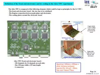
Cooling: Temperature Stabilization and Homogeneity • Clearly a challenging item: we aim at T 0.1 K • Double defense line strategy: • Outer thermal screens toward TRD and ITS • ROC al bodies and pad planes: water-cooled • Direct water cooling of FEE boards (Cu sheet sandwich) • Simulations and tests look promising • An important concern: resistor rods (4 x 8 W) ALICE TPC, Schleching 2003
TPC Cooling Scheme ALICE TPC, Schleching 2003
Resistor Rod Cooling 10 Resistor Ceramic pipe Resistor G10 Separator Cu-heat bridges gnd 100 kV • gas cooled • water cooled • High-resistivity water insulation volume (gas) ALICE TPC, Schleching 2003
TPC Gas System • Ne/CO2 (90/10),high purity: < 5 ppm O2 • expensive gas -> recirculation, • low purge, ‘breathing’ system ALICE TPC, Schleching 2003
FEE Architecture Digital Circuit FEC (Front End Card) - 128 CHANNELS (CLOSE TO THE READOUT PLANE) DETECTOR Power consumption: < 40 mW / channel L1: 5ms 200 Hz 8 CHIPS x 16 CH / CHIP 8 CHIPS x 16 CH / CHIP drift region 88ms L2: < 100 ms 200 Hz gating grid PASA ADC RAM anode wire DDL (4096 CH / DDL) 570132 PADS CUSTOM IC (CMOS 0.35mm) pad plane CUSTOM IC (CMOS 0.25mm ) CSA SEMI-GAUSS. SHAPER 1 MIP = 4.8 fC S/N = 30 : 1 DYNAMIC = 30 MIP BASELINE CORR. TAIL CANCELL. ZERO SUPPR. 10 BIT < 10 MHz MULTI-EVENT MEMORY GAIN = 12 mV / fC FWHM = 190 ns ALICE TPC, Schleching 2003
Mounting FEE FRONT VIEW 36 sectors SIDE VIEW 128 channels Front End Card (FEC) C6 : 20 FECs OROC C5 : 20 FECs 190mm C4 : 20 FECs FEC C3 : 18 FECs 140mm C2 : 25 FECs Capton Cable IROC C1 : 18 FECs FEE POWER: • CHANNEL: 40 mW • BOARD: 6.9 W • SECTOR: 832 W • TOTAL: 30.2 kW ALICE TPC, Schleching 2003
Global Architecture PASA – ADC – DIG. Detector Link (100 MB / s) (#216) Each TPC Sector is served by 6 Readout Subsystems ON DETECTOR COUNTING ROOM Front-end bus (160 MB / sec) FEC 128 ch 25 RCU Data Compr. DDL - INT FEC 128 ch 2 BOARD CTRL Slow-Control Interface Local Controller Slow – Control (1 Mbit – serial link) FEC 128 ch 1 TTC-RX Local Slow- Control Serial link Overall TPC: 4356 Front End Cards 216 Readout Control Units ALICE TPC, Schleching 2003
Differential PASA Circuit ALICE TPC, Schleching 2003
Differential Output Signal ALICE TPC, Schleching 2003
Noise performance of PASA ALICE TPC, Schleching 2003
Differential PASA Test Results ALICE TPC, Schleching 2003
ALICE TPC READOUT CHIP– Principle 10-bit arithmetic 10- bit 20 MSPS 11- bit CA2 arithmetic 18- bit CA2 arithmetic 11- bit arithmetic 40-bit format 40-bit format SAMPLING CLOCK 20 MHz READOUT CLOCK 40 MHz ALICE TPC, Schleching 2003
ALTRO – Summary of Prototyping 4 PQFP 100 8 SSOP 28 4cards 16 ch 20 mm ALTRO 16 External ADCs (fallback solution) 135 mm 24 mm IntegratedADCs 1999 channels per chip: 4 ADC: 4 external Digital Filter: no 2001 channels per chip: 16 ADC: 16 internal Digital Filter: yes 1998 channels per chip: 1 ADC: 1 external Digital Filter: no ALICE TPC, Schleching 2003
ALTRO Layout and Package 14.1 mm 12 mm 7.7 mm 24mm ADC Channel 0 TQFP 176 3.8 mm 8.3 mm ADC Channel 7 Pedestal Memory 1K x 10 2.5 m (ST) Data Memory 1K x 40 Processing Logic ALICE TPC, Schleching 2003
ALTRODigital Tail Cancellation Performance ADC counts Time samples (170 ns) ADC counts Time samples (170 ns) ALICE TPC, Schleching 2003