Download
1 / 29
300 likes | 438 Views
This presentation explores advanced fusion reactor models focused on optimizing power output and efficiency. Specifically, it investigates four main designs: WCLL, HCPB, Dual-Coolant (DC), and Self-Cooled (SC) systems, emphasizing the interplay between coolant types and overall plant performance. Design requirements are outlined for achieving 1.5 GWe, addressing aspects such as modular blanket construction, thermal management, and waste reduction. Key parameters including thermal efficiency, neutron load, and operational safety are critically analyzed to ensure reliability and performance in future fusion energy systems.

E N D
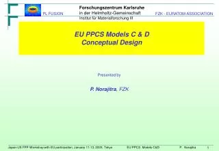
Institut für Materialforschung III EU PPCS Models C & DConceptual Design Presented by P. Norajitra, FZK
PPCS Design Studies – Strategy definition [D. Maisonnier] 2 models with “limited” extrapolations • Model A: WCLL (water cooled lithium lead) [P. Sardain] • Model B: HCPB (helium cooled pebble bed) [S. Hermsmeyer] • Divertor coolant = blanket coolant • Normalised gross electric power output of 1.5 GWe 2 more “advanced” models • Model C: DC (dual coolant: helium and lithium lead) [P. Norajitra] • Model D: SC (self cooled: lithium lead) [L. Giancarli] • Divertor coolant = blanket coolant (C: He, D: PbLi) • Normalised gross electric power output of 1.5 GWe
Materials basis W/ODS/He ODS / RAFM W/SiC/LiPb (He opt.) SiC
Engineering Parameters Basic Parameters Physics Parameters Unit Size [GWe] HH (IPB98y2) Fusion Power [GW] (after iteration) 1.5 1.3 3.45 Major Radius [m] n/nG Source peaking factor 7.5 2.5 1.5 Aspect Ratio N(thermal, total) Heating Power [MW] 3.7, 4.0 3.0 112 Bootstrap fraction Plasma Current [MA] Average neutron wall load [MW/m2] 2.25 0.63 19.0 Safety factor q(95) TF on axis [T] FW Surface Heat Flux [MW/m2] 6.0 0.5 4.5 Number of TF coils Max. Divertor Heat Load [MW/m2] Zeff 2.2 10 16 Average Electron Temp. [keV] TF on TF Coil Conductor [T] 13.6 16 Elongation (X-point, 95% flux) 2.1, 1.9 Temperature peaking factor 1.5 Triangularity (X-point, 95% flux) 0.7, 0.47 Density peaking factor 0.5 Q 34 Model C reactor (DC blanket) – Main parameters
Institut für Materialforschung III PPCS – Model C&D: General design requirements • 1.5 GWeelectricpower output • Small reactor dimension (minimization of the plant costs) • High efficiency (low cost of electricity) • High reliability and availability • Easy blanket replacement • Reduction ofwastes quantities
Institut für Materialforschung III PPCS – Model C&D: Response for detail design • Small radial blanket thickness, however must be ensured: • TBR > 1 and sufficient n-shielding • As high an coolantoutlet temperature as possible, however: • No excess of the permissible structure temperature, (C): 550°C for EUROFER) as well as the corrosion temperature PbLi/Steel (approx. 500°C) • Thermohydrualics and MHD appropriate design with small pressure losses • Homogeneous structure temperature distribution • Simple construction, as much as possible permanent parts
pol. rad. tor. Model C: Main design features Structure • Modular blanket design (permanent ‘P’ and exchangeable ‘E’ parts) • The basis blanket structure is made of EUROFER • 2-3 mm ODS layer is plated onto the plasma facing FW surface, utilising high temperature strength of ODS (and getting rid of ODS welding problems) Flow channel inserts (FCI) • SiCf/SiC FCI for electrical (MHD reduction) and thermal insulation (high Pb17Li exit temperature, e.g. 700°C for higher thermal efficiency), no structural functions Dual-Coolants He/PbLi • FW and steel grids are cooled by 8 MPa He • Self-cooled Pb17Li acting as breeder and coolant E P P DC outboard blanket (cut-out at torus centre)
Model C: Modular design with permanent and exchangeable parts 16 TF coils coolant manifolds (d) (permanent) 8 upper ports (f) (modules & coolant) c 5 f 6 4 176 blanket modules (a) (5-6 yrs. lifetime) 7 3 a d 8 9 2 g 8 central ports (g) (modules) 1 10 b e 11 vacuum vessel 70 cm (e) (permanent) cold shield 30 cm (c) (permanent) h 48 divertor plates (b) (1-2 yrs. lifetime) lower divertor ports (h) (8 remote handling, 16 coolant)
Model C - The radial build [D. Ward] Iterative approach betw. design and system code In-/Outb. blanket thickness (incl. shield): 1.1 / 1.6 (m)
Model C - Size, weight, power, and required mass flow rates of the modules (IB = inboard, OB = outboard); Total number of module = 11 x 16 = 176
Model C : DC Blanket Neutronic Model and Results TBR = 1.15[U. Fischer] (90% 6Li, inb/outb breeder zone thk: 50.5/85.5 cm)
Institut für Materialforschung III Replacement path of blanket modules and divertor cassettes
Institut für Materialforschung III Model C: Integration of He-cooled divertor • 10 MW/m2 (PPCS) • W tile as thermal shield (5 mm thick) • W-1%La2O3 cooling finger (thimble) • RAFM (HT)ODS Eurofer structure • THe, inl/outl = 700/800 °C (target plate) (in this study advanced HT ODS was assumed) presentation by L. Boccaccini
Model C: Dual Coolant Systems Blanket & Divertor Circuits Characteristics (4 parallel Brayton cycles – He turbine) Power Plant Layout Blanket Divertor
Model C reactor – Main key issues and R&D needs • SiC/SiC related issues: Flow Channel Inserts design (out of the main body) and fabrication, irradiation effects, compatibility with high v, high T LiPb • MHD: modeling and computations of 3D inertial flow in expansion • ODS: fabrication of ODS plated FW, irradiation effects • Tritium recovery and LiPb purification: identification/demonstration of acceptable techniques • Heat exchanger technology (for LiPb): to be defined • Blanket system design: some integration aspects not solved or not addressed (because of lack of time) • Divertor: He-cooled W-structures (see following presentation)
Engineering Parameters Basic Parameters Physics Parameters Unit Size [GWe] HH (IPB98y2) Fusion Power [GW] (after iteration) 1.5 1.2 2.53 Major Radius [m] n/nG Source peaking factor 6.1 2.5 1.5 Aspect Ratio N(thermal, total) Heating Power [MW] 3.7, 4.5 3.0 71 Bootstrap fraction Plasma Current [MA] Average neutron wall load [MW/m2] 2.4 0.76 14.1 Safety factor q(95) TF on axis [T] FW Surface Heat Flux [MW/m2] 5.6 0.5 4.5 Number of TF coils Max. Divertor Heat Load [MW/m2] Zeff 1.6 5 16 Average Electron Temp. [keV] TF on TF Coil Conductor [T] 13.4 12 Elongation (X-point, 95% flux) 2.1, 1.9 Temperature peaking factor 1.5 Triangularity (X-point, 95% flux) 0.7, 0.47 Density peaking factor 0.5 Q 35 Model D reactor (SCLL blanket) – Main parameters
Model D reactor – Major design choices • Structural Material: SiC/SiC for both Blanket and Divertor (low act., high T) • Blanket working principle: co-axial Pb-17Li flow to maximize outlet T • Divertor working principle: use of independent Pb-17Li coolant circuit, to minimize pressure/avoid structural W (NB: He-cooled divertor needs different optimization) • Pb-17Li external circuits location: horizontal deployment, to minimize pressure • Blanket remote maintenance procedure: segment geometry, maintained through vertical ports after Pb-17Li draining • Divertor remote maintenance procedure: as in ITER • Potential reduction of waste quantities: separation of outboard blanket in two zones in order to minimize radioactive waste (depending on lifetime evaluations) • Magnet system: possibility of high T superconductors (77 K) • Plasma heating system: acknowledge of need but not evaluated • Advanced conversion systems: potential for H-production
Self-Cooled Lithium-Lead blanket& divertor (SCLL) general characteristics • segment : SiCf/SiC box acting as Pb-17Li container, 2 mm W protection • use of 3D (industrial) SiCf/SiC 3D , extensive use of brasing • Pb-17Li: Tinlet/outlet 700°C/1100°C (div: 600/990°C), max. speed ~4.5 m/s • dimensions outboard (front) segments: 5 modules h=8m, w=0.3m, thk=0.3m • High T Shield: Pb-17Li-cooled WC, SiCf/SiC structures (energy recovered) • Low T Shield: He-cooled WC with B-steel structures (as for VV) main performances • Neutronics : TBR = 1.12 (0.98 blankets, 0.125 divertor, 0.015 HT shield) • Thermal results : Tmax ~1100°C (if l =20 W/mK, thk. FW 6 mm) • Acceptable stresses (see criteria details) for Hydr. pressure = 0.8 MPa • Acceptable MHD pressure drops • 1 independent cooling circuit for divertor, 4 for blanket, e = 61 % (Pel/Pfus) • T-extraction performed on the cold leg (Pb-17Li renewal ~1100 times/day)
P1=2 Primary pumps 50% 12” Pb-17Li C C C T 20” 4” 4” He 20” p 2” GS 10” p 2” 10” pump Cooling Water 20” Model D : SCLL T-extraction and PbLi purification systems He-detritiation system BLANKET He+Tritium T extractor Pb-17Li purification Pb-17Li tank
Sect. A-A Sect. C-C C 5.5 1.4 1.1 1 1 B B 5.5 30 B 2 r r p C 12.8 2 31.8 p t t Sect. B-B A A Model D : SCLL Divertor (details)
Model D reactor – Main key issues and R&D needs • SiC/SiC related issues: structural functions, assumed extrapolated properties for design, several aspects can be critical properties under irradiation (i.e., thermal conductivity, burn-up, lifetime) fabrication (brazing, weaving, pipe connections) properties reliability, behavioral modeling, compatibilitywith high v & T LiPb • MHD: modeling and computations of 3D inertial flow in expansion • Tritium recovery and LiPb purification: identification/demonstration of acceptable techniques for high flow rates (>1000 LiPb recirculations per day) • Heat exchanger technology: to be defined, SiC/SiC structures probably needed • External circuits: SiC/SiC structures probably needed, basic components not available • Blanket system design: several integration aspects not solved or not addressed (because of lack of time) • Divertor: LiPb-cooled SiC/SiC structures, fabrication to be defined, impact of irradiation (not taken into account) very critical