Modeling & Analysis
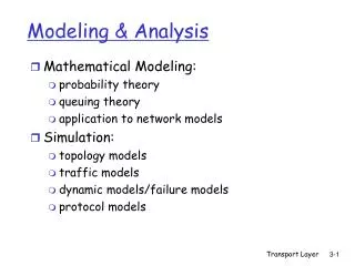
Modeling & Analysis. Mathematical Modeling: probability theory queuing theory application to network models Simulation: topology models traffic models dynamic models/failure models protocol models. Simulation tools. VINT (Virtual InterNet Testbed):

Modeling & Analysis
E N D
Presentation Transcript
Modeling & Analysis • Mathematical Modeling: • probability theory • queuing theory • application to network models • Simulation: • topology models • traffic models • dynamic models/failure models • protocol models Transport Layer
Simulation tools • VINT (Virtual InterNet Testbed): • catarina.usc.edu/vint [USC/ISI, UCB,LBL,Xerox] • network simulator (NS), network animator (NAM) • library of protocols: • TCP variants • multicast/unicast routing • routing in ad-hoc networks • real-time protocols (RTP) • …. Other channel/protocol models & test-suites • extensible framework (Tcl/tk & C++) • Check the ‘Simulator’ link thru the class website Transport Layer
OPNET: • commercial simulator • strength in wireless channel modeling • GlomoSim (QualNet): UCLA, parsec simulator • Research resources: • ACM & IEEE journals and conferences • SIGCOMM, INFOCOM, Transactions on Networking (TON), MobiCom • IEEE Computer, Spectrum, ACM Communications magazine • www.acm.org, www.ieee.org Transport Layer
Modeling using queuing theory • Let: • N be the number of sources • M be the capacity of the multiplexed channel • R be the source data rate • be the mean fraction of time each source is active, where 0<1 Transport Layer
if N.R=M then input capacity = capacity of multiplexed link => TDM • if N.R>M but .N.R<M then this may be modeled by a queuing system to analyze its performance Transport Layer
Queuing system for single server Transport Layer
is the arrival rate • Tw is the waiting time • The number of waiting items w=.Tw • Ts is the service time • is the utilization ‘fraction of the time the server is busy’, =.Ts • The queuing time Tq=Tw+Ts • The number of queued items (i.e. the queue occupancy) q=w+=.Tq Transport Layer
=.N.R, Ts=1/M • =.Ts=.N.R.Ts=.N.R/M • Assume: - random arrival process (Poisson arrival process) • constant service time (packet lengths are constant) • no drops (the buffer is large enough to hold all traffic, basically infinite) • no priorities, FIFO queue Transport Layer
Inputs/Outputs of Queuing Theory • Given: • arrival rate • service time • queuing discipline • Output: • wait time, and queuing delay • waiting items, and queued items Transport Layer
Queue Naming: X/Y/Z • where X is the distribution of arrivals, Y is the distribution of the service time, Z is the number of servers • G: general distribution • M: negative exponential distribution • (random arrival, poisson process, exponential inter-arrival time) • D: deterministic arrivals (or fixed service time) Transport Layer
M/D/1: • Tq=Ts(2-)/[2.(1-)], • q=.Tq=+2/[2.(1-)] Transport Layer
As increases, so do buffer requirements and delay • The buffer size ‘q’ only depends on Transport Layer
Queuing Example • If N=10, R=100, =0.4, M=500 • Or N=100, M=5000 • =.N.R/M=0.8, q=2.4 • a smaller amount of buffer space per source is needed to handle larger number of sources • variance of q increases with • For a finite buffer: probability of loss increases with utilization >0.8 undesirable Transport Layer
Chapter 3Transport Layer Computer Networking: A Top Down Approach 4th edition. Jim Kurose, Keith RossAddison-Wesley, July 2007. Computer Networking: A Top Down Approach, 5th edition. Jim Kurose, Keith RossAddison-Wesley, April 2009. Transport Layer
Our goals: understand principles behind transport layer services: Multiplexing, demultiplexing reliable data transfer flow control congestion control learn about transport layer protocols in the Internet: UDP: connectionless transport TCP: connection-oriented transport TCP congestion control Chapter 3: Transport Layer Transport Layer
3.1 Transport-layer services 3.2 Multiplexing and demultiplexing 3.3 Connectionless transport: UDP 3.4 Principles of reliable data transfer 3.5 Connection-oriented transport: TCP segment structure reliable data transfer flow control connection management 3.6 Principles of congestion control 3.7 TCP congestion control Chapter 3 outline Transport Layer
provide logical communication between app processes running on different hosts transport protocols run in end systems send side: breaks app messages into segments, passes to network layer rcv side: reassembles segments into messages, passes to app layer more than one transport protocol available to apps Internet: TCP and UDP application transport network data link physical application transport network data link physical logical end-end transport Transport services and protocols Transport Layer
reliable, in-order delivery to app: TCP congestion control flow control connection setup unreliable, unordered delivery to app: UDP no-frills extension of “best-effort” IP services not available: delay guarantees bandwidth guarantees application transport network data link physical application transport network data link physical network data link physical network data link physical network data link physical network data link physical network data link physical network data link physical logical end-end transport Internet transport-layer protocols Transport Layer
3.1 Transport-layer services 3.2 Multiplexing and demultiplexing 3.3 Connectionless transport: UDP 3.4 Principles of reliable data transfer 3.5 Connection-oriented transport: TCP segment structure reliable data transfer flow control connection management 3.6 Principles of congestion control 3.7 TCP congestion control Chapter 3 outline Transport Layer
Multiplexing at send host: Demultiplexing at rcv host: Multiplexing/demultiplexing delivering received segments to correct socket gathering data from multiple sockets, enveloping data with header (later used for demultiplexing) = socket = process application P4 application application P1 P2 P3 P1 transport transport transport network network network link link link physical physical physical host 3 host 2 host 1 Transport Layer
host receives IP datagrams each datagram has source, destination IP addresses each datagram carries 1 transport-layer segment each segment has source, destination port numbers host uses IP addresses & port numbers to direct segment to appropriate socket, process, application How demultiplexing works: General for TCP and UDP 32 bits source port # dest port # other header fields application data (message) TCP/UDP segment format Transport Layer
Create sockets with port numbers: DatagramSocket mySocket1 = new DatagramSocket(12534); DatagramSocket mySocket2 = new DatagramSocket(12535); UDP socket identified by two-tuple: (dest IP address, dest port number) When host receives UDP segment: checks destination port number in segment directs UDP segment to socket with that port number IP datagrams with different source IP addresses and/or source port numbers directed to same socket Connectionless demultiplexing Transport Layer
P3 P2 P1 P1 SP: 9157 client IP: A DP: 6428 Client IP:B server IP: C SP: 5775 SP: 6428 SP: 6428 DP: 6428 DP: 9157 DP: 5775 Connectionless demux (cont) DatagramSocket serverSocket = new DatagramSocket(6428); SP provides “return address” Transport Layer
TCP socket identified by 4-tuple: source IP address source port number dest IP address dest port number recv host uses all four values to direct segment to appropriate socket Server host may support many simultaneous TCP sockets: each socket identified by its own 4-tuple Web servers have different sockets for each connecting client non-persistent HTTP will have different socket for each request Connection-oriented demux Transport Layer
SP: 9157 SP: 5775 P1 P1 P2 P4 P3 P6 P5 client IP: A DP: 80 DP: 80 Connection-oriented demux (cont) S-IP: B D-IP:C SP: 9157 DP: 80 Client IP:B server IP: C S-IP: A S-IP: B D-IP:C D-IP:C Transport Layer
3.1 Transport-layer services 3.2 Multiplexing and demultiplexing 3.3 Connectionless transport: UDP 3.4 Principles of reliable data transfer 3.5 Connection-oriented transport: TCP segment structure reliable data transfer flow control connection management 3.6 Principles of congestion control 3.7 TCP congestion control Chapter 3 outline Transport Layer
“no frills,” “bare bones” transport protocol “best effort” service, UDP segments may be: lost delivered out of order to app connectionless: no handshaking between UDP sender, receiver each UDP segment handled independently Why is there a UDP? no connection establishment (which can add delay) simple: no connection state at sender, receiver small segment header no congestion control: UDP can blast away as fast as desired (more later on interaction with TCP!) UDP: User Datagram Protocol [RFC 768] Transport Layer
often used for streaming multimedia apps loss tolerant rate sensitive other UDP uses DNS SNMP (net mgmt) reliable transfer over UDP: add reliability at app layer application-specific error recovery! used for multicast, broadcast in addition to unicast (point-point) UDP: more 32 bits source port # dest port # Length, in bytes of UDP segment, including header checksum length Application data (message) UDP segment format Transport Layer
3.1 Transport-layer services 3.2 Multiplexing and demultiplexing 3.3 Connectionless transport: UDP 3.4 Principles of reliable data transfer 3.5 Connection-oriented transport: TCP segment structure reliable data transfer flow control connection management 3.6 Principles of congestion control 3.7 TCP congestion control Chapter 3 outline Transport Layer
important in app., transport, link layers top-10 list of important networking topics! characteristics of unreliable channel will determine complexity of reliable data transfer protocol (rdt) Principles of Reliable data transfer Transport Layer
important in app., transport, link layers top-10 list of important networking topics! characteristics of unreliable channel will determine complexity of reliable data transfer protocol (rdt) Principles of Reliable data transfer Transport Layer
important in app., transport, link layers top-10 list of important networking topics! characteristics of unreliable channel will determine complexity of reliable data transfer protocol (rdt) Principles of Reliable data transfer Transport Layer
rdt_send():called from above, (e.g., by app.). Passed data to deliver to receiver upper layer deliver_data():called by rdt to deliver data to upper udt_send():called by rdt, to transfer packet over unreliable channel to receiver rdt_rcv():called when packet arrives on rcv-side of channel Reliable data transfer: getting started send side receive side Transport Layer
Flow Control • End-to-end flow and Congestion control study is complicated by: • Heterogeneous resources (links, switches, applications) • Different delays due to network dynamics • Effects of background traffic • We start with a simple case: hop-by-hop flow control Transport Layer
Hop-by-hop flow control • Approaches/techniques for hop-by-hop flow control • Stop-and-wait • sliding window • Go back N • Selective reject Transport Layer
underlying channel perfectly reliable no bit errors, no loss of packets stop and wait Stop-and-wait: reliable transfer over a reliable channel Sender sends one packet, then waits for receiver response Transport Layer
underlying channel may flip bits in packet checksum to detect bit errors the question: how to recover from errors: acknowledgements (ACKs): receiver explicitly tells sender that pkt received OK negative acknowledgements (NAKs): receiver explicitly tells sender that pkt had errors sender retransmits pkt on receipt of NAK new mechanisms for: error detection receiver feedback: control msgs (ACK,NAK) rcvr->sender channel with bit errors Transport Layer
Stop-and-wait operation Summary • Stop and wait: • sender awaits for ACK to send another frame • sender uses a timer to re-transmit if no ACKs • if ACK is lost: • A sends frame, B’s ACK gets lost • A times out & re-transmits the frame, B receives duplicates • Sequence numbers are added (frame0,1 ACK0,1) • timeout: should be related to round trip time estimates • if too small unnecessary re-transmission • if too large long delays Transport Layer
Stop-and-wait with lost packet/frame Transport Layer
Stop and wait performance • utilization – fraction of time sender busy sending • ideal case (error free) • u=Tframe/(Tframe+2Tprop)=1/(1+2a), a=Tprop/Tframe Transport Layer
example: 1 Gbps link, 15 ms e-e prop. delay, 1KB packet: Performance of stop-and-wait L (packet length in bits) 8kb/pkt T = = = 8 microsec transmit R (transmission rate, bps) 10**9 b/sec • U sender: utilization – fraction of time sender busy sending • 1KB pkt every 30 msec -> 33kB/sec thruput over 1 Gbps link • network protocol limits use of physical resources! Transport Layer
stop-and-wait operation sender receiver first packet bit transmitted, t = 0 last packet bit transmitted, t = L / R first packet bit arrives RTT last packet bit arrives, send ACK ACK arrives, send next packet, t = RTT + L / R Transport Layer
Sliding window techniques • TCP is a variant of sliding window • Includes Go back N (GBN) and selective repeat/reject • Allows for outstanding packets without Ack • More complex than stop and wait • Need to buffer un-Ack’ed packets & more book-keeping than stop-and-wait Transport Layer