Download
1 / 51
920 likes | 1.7k Views
MAP PROJECTIONS. Present by : Nidal ABURAJAB. Basic Definitions. Geodesy - the shape of the earth and definition of earth datum Map Projection - the transformation of a curved surface of earth to a flat map Coordinate systems - (x,y) coordinate systems for map data.

E N D
MAP PROJECTIONS Present by : Nidal ABURAJAB
Basic Definitions • Geodesy - the shape of the earth and definition of earth datum • Map Projection - the transformation of a curved surface of earth to a flat map • Coordinate systems - (x,y) coordinate systems for map data
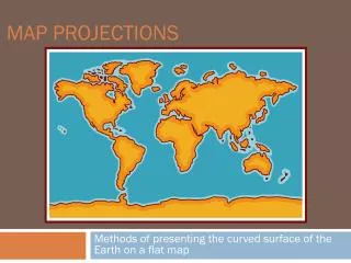
BRIEF INTRODUCTION TO MAP PROJECTIONS • Map Projection is defined as an orderly system (a mathematical model) of projecting portions of the earth’s surface to a plane or flat surface – a map. • To produce a map of the world or part of it, we make use of map projections. • Map projection is transformation between curved reference surface of the Earth & the flat plane of map. • Map projection can also be defined as a set of equations which allows us to transform a set of Geographic coordinates (Longitude, Latitude) to Cartesian Coordinates of the two dimensional surface of Earth
Map Projection ‘A map projection is a means of representing the lines of latitude and longitude of the globe on a flat sheet of paper’ J.A. Steers "a systematic drawing of parallels of latitude and meridians of longitudes on a plane surface for the whole earth or a part of it on a certain scale so that any point on the earth surface may correspond to that on the drawing."
BASIC PROBLEM OF MAP PROJECTION • The transformation from the curved surface of the Earth to the flat plane of the map is never completed successfully. Distortion after flattening a curved surface.
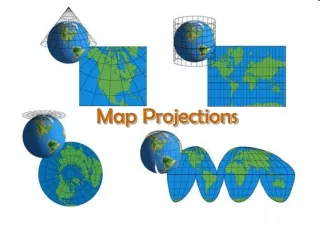
MAP PROJECTION CONCEPTS • The concept of projecting is required to express three dimensional space as a two dimensional map. • One easy way to understand is visualize projecting a light through the Earth onto a surface. • Only a few map projections are actually produced by direct projection.
SCALE DISTORTION • It is impossible to project the Earth on a piece of paper without location distortions. No scale distortion No scale distortion No scale distortion Most distortion Most distortion Most distortion Most distortion Earth surface Earth surface Tangent map plane Secant map plane • It is important to know the extent to which the scale varies on map.
Projection Properties On the globe, places and areas contain the properties of shape, area, direction and distance. A projection may retain one or two of these but not all, and specifically NOT both area and shape. a. Area A projection that maintains 'area' is called equal area or equivalent. That means that two equal areas on the globe are equal areas on the map. This is achieved by sacrificing shape. Stretching in one direction to counter for earth curvature must be compensated by compaction in the other.b. Shape A given shape, such as a square, maintains its shape across the map but at the cost of area and is called conformal or orthomorphic. For example a 2x2 square becomes a 1x1or 4x4 square. Stretching in one direction is matched by stretching in the other.
c. Distance Not all distances can be retained, but distances can be correct in one direction from a line. This line is called a standard line. Distance can also be correct in all directions from a point. In these cases, the projection is termed equidistant. d. Direction (azimuth) Azimuth is the compass bearing between two points. Not all azimuth can be maintained (or there would be no distortion). It can be maintained in all directions only from a point, these projections are called azimuthal.
MAP PROJECTION - Any Transformation between the curved reference surface of the earth & the flat plane of the map. - Transforms a set of ellipsoidal geographic coordinates on the reference of the earth surface to a set of Cartesian coordinates representing positions on the 2-D surface of the map. x, y = ƒ (, ) = Geographic to Cartesian , = ƒ (x, y) Inverse
Projections- used for • Conic (Albers Equal Area, Lambert Conformal Conic) - good for East-West land areas • Cylindrical (Transverse Mercator) - good for North-South land areas • Azimuthal (Lambert Azimuthal Equal Area) - good for global views
Representative Fraction Globe distanceEarth distance = Earth to Globe to Map Map Projection: Map Scale: Scale Factor Map distanceGlobe distance = (e.g. 0.9996) (e.g. 1:24,000)
Cylindrical Projections • The normal aspect for cylindrical projections assumes that the cylinder is tangent to the globe along the Equator. In this orientation, the graticule appears as a rectangular grid. In the tangent case, the Equator is true to scale and distortion increases with distance from the Equator. • In the secant case, the standard parallels which lie equidistant north and south of the Equator are true to scale and distortion increases with distance from the standard lines.
Cylindrical Projections(Mercator) Transverse Oblique
POLYCONIC PROJECTION • Class : Neither Conformal nor equal area. • Projection principle : It consists of many (poly) cones involved. The cones are tangent to each parallel, so that meridians are curved & parallels are also curved. Polyconic Projection Conic Projection Uses :- 1. All topographic maps in India are in Polyconic Projection. 2. Used for large scale mapping of USA till 1950 only. 3. Not a suitable projection for digital environment due to problem of rolling fit .
CYLINDERICAL PROJECTION Cylinder +180 -180 0 +90 Parallels and Meridians are straight line intersecting at right angles. It is conformal i.e. direction are true. Areas & distances are exaggerated near poles. Since directions are true it was used for navigational purpose since 16th century. Now often inappropriately used as world map (as pole & equator are of same size). 0 -90
UNIVERSAL TRANSVESE MERCATOR (UTM) • UTM projection is now widely used projection for topographical mapping purposes. • It is conformal cylindrical projection. • It covers almost entire world (80o S to 84o N) in 60 zones of 6o Longitude. • Reference Latitude (fo), is the equator. • Each zone has its own Central Meridian. • Each zone has its own Cartesian coordinate system.
Coordinate systems • Universal Transverse Mercator Every place on earth falls in a particular zone
Examples of different projections • Albers (Conic) Shape Shape along the standard parallels is accurate and minimally distorted in the region between the standard parallels and those regions just beyond. The 90-degree angles between meridians and parallels are preserved, but because the scale along the lines of longitude does not match the scale along lines of latitude, the final projection is not conformal. Area All areas are proportional to the same areas on the Earth. Direction Locally true along the standard parallels. Distance Distances are best in the middle latitudes. Along parallels, scale is reduced between the standard parallels and increased beyond them. Along meridians, scale follows an opposite pattern.
Examples of different projections • Lambert Azimuthal Equal Area (Planar) Shape Shape is true along the standard parallels of the normal aspect (Type 1), or the standard lines of the transverse and oblique aspects (Types 2 and 3). Distortion is severe near the poles of the normal aspect or 90° from the central line in the transverse and oblique aspects. Area There is no area distortion on any of the projections. Direction Local angles are correct along standard parallels or standard lines. Direction is distorted elsewhere. Distance Scale is true along the Equator (Type 1), or the standard lines of the transverse and oblique aspects (Types 2 and 3). Scale distortion is severe near the poles of the normal aspect or 90° from the central line in the transverse and oblique aspects.
Examples of different projections • Mercator(Cylindrical) Shape Conformal. Small shapes are well represented because this projection maintains the local angular relationships. Area Increasingly distorted toward the polar regions. For example, in the Mercator projection, although Greenland is only one-eighth the size of South America, Greenland appears to be larger. Direction Any straight line drawn on this projection represents an actual compass bearing. These true direction lines are rhumb lines, and generally do not describe the shortest distance between points. Distance Scale is true along the Equator, or along the secant latitudes.
Examples of different projections • Miller(Cylindrical) Shape Minimally distorted between 45th parallels, increasingly toward the poles. Land masses are stretched more east to west than they are north to south. Area Distortion increases from the Equator toward the poles. Direction Local angles are correct only along the Equator. Distance Correct distance is measured along the Equator.
Examples of different projections • Mollweide(Pseudo-cylindrical) Shape Shape is not distorted at the intersection of the central meridian and latitudes 40° 44' N and S. Distortion increases outward from these points and becomes severe at the edges of the projection. Area Equal-area. Direction Local angles are true only at the intersection of the central meridian and latitudes 40° 44' N and S. Direction is distorted elsewhere. Distance Scale is true along latitudes 40°44' N and S. Distortion increases with distance from these lines and becomes severe at the edges of the projection.
Examples of different projections • Orthographic Shape Minimal distortion near the center; maximal distortion near the edge. Area The areal scale decreases with distance from the center. Areal scale is zero at the edge of the hemisphere. Direction True direction from the central point. Distance The radial scale decreases with distance from the center and becomes zero on the edges. The scale perpendicular to the radii, along the parallels of the polar aspect, is accurate.
Examples of different projections • Robinson(Pseudo-cylindrical) Shape Shape distortion is very low within 45° of the origin and along the Equator. Area Distortion is very low within 45° of the origin and along the Equator. Direction Generally distorted. Distance Generally, scale is made true along latitudes 38° N and S. Scale is constant along any given latitude, and for the latitude of opposite sign.
Maps in Geographic Coordinates - Digital map data can also be stored in ‘Geographic coordinates i.e. Latitude and Longitude • Geographic coordinate system is becoming more popular in digital environment where contiguous maps are displayed on screen and measurements can be made in meters in most of GIS software. • 1:250,000 (1 x 1) or 1:50,000 scale maps get displayed as perfect squares. • The geographic system has become so popular that most of modern GIS softwares give an option whether map is to be displayed in geographic system (unprojected) or projected.
BRIEF INTRODUCTION TO DATUM • The datum for horizontal control is called ELLIPSOID. • The datum for vertical control is called GEOID.
Shape of the Earth It is actually an ellipsoidal, slightly larger in radius at the equator than at the poles We think of the earth as a sphere
Ellipse For the earth: Semi Major axis, a = 6377 km Semi Minor axis, b = 6356 km Flattening ratio, f = (a-b)/a ~ 1/300 Z b O a X F1 F2 An ellipse is defined by: Focal length = Distance (F1, P, F2) is constant for all points on ellipse When = 0, ellipse = circle P
Ellipsoid or SpheroidRotate an ellipse around an axis Z b a O Y a X Rotational axis
ELLIPSOID • The physical surface of earth which is highly irregular & hence unsuitable for computation. It is approximated by various mathematical surfaces which is known as ellipsoid. • Earth has been surveyed many times over the years . Since the shape of the earth's surface differs from one geographic area to another, different ellipsoids are used to describe particular areas to get the best fit of the area being mapped. • Ellipsoid is used as a reference surface for the determination of a location (x,y coordinates or Ф, λ). N N India Ellipsoid 1 N America Ellipsoid 2
GEOID • Geoid is equipotential surface at Mean Sea Level (MSL). It is smooth & continuous but not geometric. This surface is perpendicular to the direction of the gravity field of the Earth at all points. Due to irregular mass distribution Geoid is irregular. It is reference surface for height. Geoid
TYPE OF ELLIPSOIDS • India uses Everest Ellipsoid. • With the help of artificial satellites, earth has been observed as a whole and WGS 84 is the best fit surface for the entire globe. Name a (m) b (m) 1/f Used in Everest(1830) 6377301 6356100 300.8017 India Airy (1830) 6377563 6356257 299.32 Britain WGS 84 6378137 6356752 298.257 Global Ref: Snyder, Map Projections, A working manual, US
Sea surface Ellipsoid Earth surface Geoid Representations of the Earth Mean Sea Level is a surface of constant gravitational potential called the Geoid
Geoid and Ellipsoid Earth surface Ellipsoid Ocean Geoid Gravity Anomaly
Types of Coordinate Systems • (1) Global Cartesian coordinates (x,y,z) for the whole earth • (2) Geographic coordinates (f, l, z) • (3) Projected coordinates (x, y, z) on a local area of the earth’s surface
Z Greenwich Meridian O • Y X Equator Global Cartesian Coordinates (x,y,z)
Geographic Coordinates (f, l, z) • Latitude (f) and Longitude (l) defined using an ellipsoid, an ellipse rotated about an axis • Elevation (z) defined using geoid, a surface of constant gravitational potential