Download
1 / 7
70 likes | 223 Views
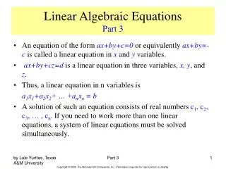
Part IA Paper 3 Linear Circuits and Devices. A simple radio receiver David Holburn dmh@eng.cam.ac.uk. You can find a pointer to an HTML version of this presentation at : http://www.eng.cam.ac.uk/~dmh. Simplest AM radio receiver. The simplest possible radio receiver

E N D
Part IA Paper 3Linear Circuits and Devices A simple radio receiver David Holburn dmh@eng.cam.ac.uk You can find a pointer to an HTML version of this presentation at: http://www.eng.cam.ac.uk/~dmh
Simplest AM radio receiver • The simplest possible radio receiver • Often called a crystal set (historic origin) • Tuner - resonant LC circuit selects required frequency (station) • Detector - separates modulated audio signal from high frequency carrier • Earphone – converts electrical signal to sound
Historic Radio Receiver (Crystal Set) The inductor is clearly visible at the rear of the baseboard. You can see the detector at left front. Terminals for headphones are visible on the right. Above: the detector - a fine crystal of galena (lead sulphide). A a fine wire or cat's whisker rests gently on its surface to made a rectifying contact.
Crystal Set Schematic • Here’s the schematic … • A parallel LC resonant circuit is used to select the required frequency • A pn junction diode is used as detector • Capacitor Cf bypasses radio frequencies to Earth • Lower frequency audio signals pass through the headphones • The headphones behave like a high value resistance
Analysis of LC circuit with pSpice • L1 and C1 chosen for resonance in Medium Wave (550 – 1600 kHz) band • V1 represents antenna signal coupled to the resonant circuit via C3 • R4 is the inductor’s resistance • R1 is in JFET amplifier (gate resistor) • Output plotted vs. frequency of 100V incoming signal • Note the narrow steep-sided resonance curve
Detector Amplitude modulation • Without the detector, the high-frequency alternating signal would not produce any audible output from the headphones. • A pn-junction diode detector is used to extract the modulated audio signal • Basic property of diode – current flows essentially in one direction • –ve half-cycles blocked by the diode • +ve half-cycles pass unimpeded • A capacitor is needed to smooth the resultant rectified waveform • Headphones convert the electrical signal back into sound