
Chapter 6
Chapter 6. Dynamic analysis of switching converters. Overview. Continuous-Time Linear Models Switching converter analysis using classical control techniques Averaged switching converter models Review of negative feedback using classical-control techniques Feedback compensation

Chapter 6
E N D
Presentation Transcript
Chapter 6 Dynamic analysis of switching converters
Overview • Continuous-Time Linear Models • Switching converter analysis using classical control techniques • Averaged switching converter models • Review of negative feedback using classical-control techniques • Feedback compensation • State-space representation of switching converters • Input EMI filters Dynamic analysis of switching converters
Overview • Discrete-time models • Continuous-time and discrete-time domains • Continuous-time state-space model • Discrete-time model of the switching converter • Design of a discrete control system with complete state feedback Dynamic analysis of switching converters
Dynamic analysis • Dynamic or small-signal analysis of the switching converter enables designers to predict the dynamic performance of the switching converter to reduce prototyping cost and design cycle time • Dynamic analysis can be either numerical or analytical Dynamic analysis of switching converters
Dynamic analysis • Switching converters are non-linear time-variant circuits • Nevertheless, it is possible to derive a continuous time-invariant linear model to represent a switching converter • Continuous-time models are easier to handle, but not very accurate • Since a switching converter is a sampled system, a discrete model gives a higher level of accuracy Dynamic analysis of switching converters
Linear model of a switching converter Dynamic analysis of switching converters
PWM modulator model Voltage-mode control Sensitivity of the duty cycle with respect to vref Dynamic analysis of switching converters
PWM modulator model Current- mode control Variation of the duty cycle due to a perturbation in the inductor current Dynamic analysis of switching converters
PWM modulator model Current- mode control Variation of the duty cycle due to a perturbation in the output voltage Dynamic analysis of switching converters
PWM modulator model Current- mode control Variation of the duty cycle due to a perturbation on the peak current Dynamic analysis of switching converters
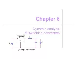
Averaged switching converter models Averaged-switch model for voltage-mode control Three-terminal averaged-switch model Dynamic analysis of switching converters
Averaged switching converter models Examples of switching converters with an averaged switch Dynamic analysis of switching converters
Averaged switching converter models Small-signal averaged-switch model for the discontinuous mode Dynamic analysis of switching converters
Averaged switching converter models Small-signal model for current-mode control Dynamic analysis of switching converters
Output filter model Output filter of a switching converter Dynamic analysis of switching converters
Output filter model Magnitude response of the output filter for several values of the output resistance Ro Dynamic analysis of switching converters
Output filter model Phase response of the output filter for several values of the output resistance Ro Dynamic analysis of switching converters
Output filter model Output filter with a capacitor Resr Dynamic analysis of switching converters
Output filter model Magnitude response of an output filter with a capacitor having a Resr for several values of the output resistance Ro Dynamic analysis of switching converters
Output filter model Phase response of an output filter with a capacitor having a Resr for several values of the output resistance Ro Dynamic analysis of switching converters
Example 6.4 • The boost converter shown in Figure 2.10 has the following parameters: Vin = 10 V, Vo = 20 V, fs = 1 kHz, L = 10 mH, C = 100 µF and RL = 20 Ω. The reference voltage is 5 V. The converter operates in the continuous-conduction mode under the voltage-mode. Using (a) the averaged-switch model, calculate the output-to-control transfer function, and (b) Matlab to draw the Bode plot of the transfer function found in (a) . Dynamic analysis of switching converters
Example 6.4 (a) The nominal duty cycle can be calculated as for the given input and output voltages, we have D=0.5. Small-signal model of the boost converter Dynamic analysis of switching converters
Example 6.4 Dynamic analysis of switching converters
Example 6.4 Bode plot of the small-signal transfer function of the boost converter Dynamic analysis of switching converters
Small-signal models of switching converters Dynamic analysis of switching converters
Small-signal models of switching converters Dynamic analysis of switching converters
Small-signal models of switching converters Dynamic analysis of switching converters
Small-signal models of switching converters Dynamic analysis of switching converters
Small-signal models of switching converters Dynamic analysis of switching converters
Small-signal models of switching converters Dynamic analysis of switching converters
Small-signal models of switching converters Dynamic analysis of switching converters
Small-signal models of switching converters Dynamic analysis of switching converters
Review of negative feedback Block diagram representation for a closed-loop system Dynamic analysis of switching converters
Review of negative feedback • Closed-loop gain • Loop gain • For TL>>1 • Stability analysis Dynamic analysis of switching converters
Relative stability Definitions of gain and phase margins Dynamic analysis of switching converters
Relative stability Loop gain of a system with three poles Dynamic analysis of switching converters
Closed-loop switching converter Dynamic analysis of switching converters
Feedback network Dynamic analysis of switching converters
Error amplifier compensation networks PI Compensation network The total phase lag Dynamic analysis of switching converters
Error amplifier compensation networks Frequency response of the PI compensation network Dynamic analysis of switching converters
Error amplifier compensation networks Phase response of the PI compensation network Dynamic analysis of switching converters
Error amplifier compensation networks PID Compensation network Dynamic analysis of switching converters
Error amplifier compensation networks Magnitude response of the PID compensation network Dynamic analysis of switching converters
Error amplifier compensation networks Magnitude response of the PID compensation network Dynamic analysis of switching converters
Error amplifier compensation networks Phase response of the PID compensation network Dynamic analysis of switching converters
Error amplifier compensation networks Asymptotic approximated magnitude response of the PID compensation network Dynamic analysis of switching converters
Compensation in a buck converter with output capacitor ESR average output voltage: 5 V input voltage: 12 Vload resistance RL = 5 Ω Design the compensation to shape the closed-loop magnitude response of the switching converter to achieve a -20 dB/decade roll-off rate at the unity-gain crossover frequency with a sufficient phase margin for stability Dynamic analysis of switching converters
Compensation in a buck converter with output capacitor ESR • f1, is chosen to be one-fifth of the switching frequency Dynamic analysis of switching converters
Compensation in a buck converter with output capacitor ESR Magnitude response of the buck converter open-loop (ABCD)closed-loop (JKLMNO)error amplifier EFGH Dynamic analysis of switching converters
Compensation in a buck converter with output capacitor ESR Dynamic analysis of switching converters


