Download
1 / 58
580 likes | 707 Views
Rainer Wallny Silicon Detector Workshop at UCSB May 11th, 2006 Slides ruthlessly stolen from: Paula Collins, CERN Alan Honma, CERN Christian Joram, CERN Michael Moll, CERN Steve Worm, RAL.

E N D
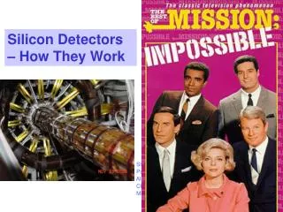
Rainer Wallny Silicon Detector Workshop at UCSB May 11th, 2006 Slides ruthlessly stolen from: Paula Collins, CERN Alan Honma, CERN Christian Joram, CERN Michael Moll, CERN Steve Worm, RAL Silicon Detectors – How They Work
Outline • Why Silicon ? • Semiconductor Basics • Band-gap, PN junction • Silicon strip detectors • Some Technicalities - Wafer Production - Wire Bonding • Radiation Damage • Effect on Vd • Effect on Leakage Currents • Conclusions
Tracking Chambers with Solid Media Ionization chamber medium could be gas, liquid, or solid Some technologies (ie. bubble chambers) not applicable in collider environments Gas Liquid Solid Density Low Moderate High Atomic number Low Moderate Moderate Ionization Energy Moderate Moderate Low Signal Speed Moderate Moderate Fast • High-precision tracking advantages with solid media • Easily ionized, relatively large amount of charge • Locally high density means less charge spreading • Fast readout possible “Solid-state detectors require high-technology devices built by specialists and appear as black boxes with unchangeable characteristics.” -Tom Ferbel, 1987 3
Why Silicon? • Electrical properties are good • Forms a native oxide with excellent electrical properties • Ionization energy is small enough for easy ionization, yet large enough to maintain a low dark current • Mechanical properties are good • Easily patterned and read out at small dimensions • Can be operated in air and at room temperature • Can assemble into complex geometries • Availability and experience • Significant industrial experience and commercial applications • Readily available at your nearest beach 4
The Idea is Not Quite New … Semiconductors used since 50’s for energy measurement in nuclear physics • Precision position measurements up until 70’s done with emulsions or bubble chambers -> limited rates, no triggering • Traditional gas detectors: limited to 50-100 μm • First silicon usage for precision position measurement: NA11 at CERN, 1981
Pioneering Silicon Strip Detectors E706 (FNAL 1987) NA11 (CERN 1981) sensor • 24x36 mm2 active area • 8 layers of silicon • 1m2 readout electronics! fan out to readout electronics • 50x50 mm2 active area Silicon sensor and readout electronics technology closely coupled • with electronics miniaturization (transistors, ICs, ASICs …) silicon quickly took off … 6
Contemporary Silicon Modules Silicon sensor and readout chip development intimately related BUT will concentrate on silicon only here … CDF SVX IIa half-ladder: two silicon sensors with readout electronics (SVX3b analog readout chip) mounted on first sensor ATLAS SCT barrel module: four silicon sensors with center-tapped readout electronics (ABCD binary readout chip) 7
Large ‘Contemporary’ Silicon Systems DELPHI (1996) ~ 1.8m2 silicon area 175 000 readout channels CMS Silicon Tracker (~2007) ~12,000 modules ~ 223 m2 silicon area ~25,000 silicon wafers ~ 10M readout channels CDF SVX IIa (2001-) ~ 11m2 silicon area ~ 750 000 readout channels 8
New Production Paradigm Systematic assembly line production with decent QA systems evolution : DELPHI (888 detectors, 8 geometries) CDF (8000 sensors, 8 geometries) CMS (25000 sensors, 15 geometries) Each sensor treated individually, nurtured into life in many hours of careful handling P. Collins, Warwick 2006
‘Moore’s Law’ for Silicon Detector Systems Moore’s Law: Exponential growth of sensitive area and number of electronic channels with time(from Computer Science: doubling of IC integration capacity every 18 months)
Large Silicon Detector Systems …. LHC Tevatron LEP Whoops… P.Collins, ICHEP 2002
Semiconductor Basics – Band Gap • In a gas, electron energy levels are discrete. In a solid, energy levels split and form a nearly-continuous band. • If the gap is large, the solid is an insulator. If there is no gap, it is a conductor. A semiconductor results when the gap is small. • For silicon, the band gap is 1.1 eV, but it takes 3.6 eV to ionize an atom. The rest of the energy goes to phonon exitations (heat).
Semiconductor Basics – Principle of Operation Basic motivation: charged particle position measurement Use ionization signal (dE/dx) left behind by charged particle passage _ + _ + _ + _ + • In a semiconductor, ionization produces electron hole pairs • Electric fields drift electrons and holes to oppositely electrodes BUT: • In pure intrinsic (undoped) silicon, many more free charge carriers than those produced by a charged particle. Have 4.5x10⁸ free charge carriers; only 3.2x10⁴ produced by MIP • Electron –hole pairs quickly re-combine … Need to deplete free charge carriers and separate e-holes ‘quickly’!
Doping Silicon n-type: • In an n-type semiconductor, negative charge carriers (electrons) are obtained by adding impurities of donor ions (eg. Phosphorus (type V)) • Donors introduce energy levels close to conduction band thus almost fully ionized => Fermi Level near CB Electrons are the majority carriers. p-type: • In a p-type semiconductor, positive charge carriers (holes) are obtained by adding impurities of acceptor ions (eg. Boron (type III)) • Acceptors introduce energy levels close to valence band thus ‘absorb’ electrons fromVB, creating holes => Fermi Level near VB. Holes are the majority carriers.
The pn-Junction Exploit the properties of a p-n junction (diode) to collect ionization charges – – p n – – – – – – – Funky cartoon from Brazil: http://www.agostinhorosa.com.br/artigos/transistor-6.html + + + + + + + + + + + + + + + + When brought together to form a junction, a gradient of electron and hole densities results in a diffuse migration of majority carriers across the junction. Migration leaves a region of net charge of opposite sign on each side, called the depletionregion (depleted of charge carriers). Electric field set up prevents further migration of carriers resulting in potential difference Vbi Another way to look at it: Fermi-Levels need to be adjusted so thus energy bands get distorted => potential Vbi
pn - Junction • p-type and n-type doped silicon forms a region that is depleted of free charge carriers • The depleted region contains a non-zero fixed charge and an electric field. In the depletionzone, electron – hole pairs won’t recombine but rather drift along field lines • Artificially increasing this depleted region by applying a reversed bias voltage allow charge collection from a larger volume p n – – – – – – – – – Dopant concentration Space charge density Carrier density Electric field Electric potential + + + + + + + + + + + + + +
How to Build a Silicon Detector If we make the p-n junction at the surface of a silicon wafer with the bulk being n-type (you could also do it the opposite way), we then need to extend the depletion region throughout the n bulk to get maximum charge collection by applying a reverse bias voltage. p p p n – h+ e- +
Properties of the Depletion Zone Depletion width is a function of the bulk resistivity , charge carrier mobility and the magnitude of reverse bias voltage Vb: Depletion zone w – Vb d w =2Vb where = 1/ q N for doped material where N is the doping concentration and q is the charge of the electron and is the carrier mobility (v= E) + undepleted zone • The bias voltage needed to completely deplete a device of thickness d is called thedepletion voltage, Vd • Need a higher voltage to fully deplete a low resistivity material. • A higher voltage is needed for a p-type bulk since the carrier mobility of holes is lower than for electrons (450 vs 1350 cm2/ V·s) Vd =d2 /(2)
Properties of the Depletion Zone (cont’d) One normally measures the depletion behavior (finds the depletion voltage) by measuring the capacitance versus reverse bias voltage. The capacitance is simply the parallel plate capacity of the depletion zone. C = A / 2Vb Vd capacitance vs voltage 1/C2 vs voltage
Leakage Current - Two main sources of (unwanted) current flow in reversed-biased diode: Diffusion current, charge generated in undepleted zone adjacent to depletion zone diffuses into depletion zone (otherwise would quickly recombine) • Generation current Jg, charge generated in depletion zone by defects/contaminants Jg exp(-b/kT) negligible in a fully depleted device Exponential dependence on temperature due to thermal dependence of e-h pair creation by defects in bulk. Rate is determined by nature and concentration of defects. 21
Bias Resistor and AC Coupling Need to isolate strips from each other and collect/measure charge on each strip => high impedance bias connection (resistor or equivalent) Usually want to AC (capacitatively) couple input amplifier to avoid large DC input from leakage current. Both of these structures are often integrated directly on the silicon sensor. Bias resistors via deposition of doped polycrystalline silicon, and capacitors via metal readout lines over the implants but separated by an insulating dielectric layer (SiO2 , Si3N4). – h+ e- +
The Charge Signal Most probable charge ≈ 0.7 x mean • Collected charge usually given for Minimum Ionizing Particle (MIP) Mean charge dE/dx)Si = 3.88 MeV/cm, for 300mmthick = 116 keV This is mean loss, for silicon detectors use most probable loss (0.7 mean) = 81 keV 3.6eV needed to make e-h pair Collected charge 22500 e (=3.6 fC)
But There Is Noizzzzzz ….. noise distribution Landau distribution with noise Landau distribution has significant low energy tail which becomes even lower with noise broadening. Noise sources: • Capacitance ENC ~ Cd • Leakage Current ENC ~ √ I • Thermal Noise ENC ~ √( kT/R) One usually has low occupancy in silicon sensors most channels have no signal. Don’t want noise to produce fake hits so need to cut high above noise tail to define good hits. But if too high you lose efficiency for real signals. Figure of Merit: Signal-to-Noise Ratio S/N. Typical Values ~ 10-15, people get nervous below 10.Radiation Damage can degrade the S/N. Thus S/N determines detector lifetime in radiation environment.
Charge Collection and Diffusion Drift velocity of charge carriers v = E, so drift time,td = d/v = d/E Typical values: d=300 m, E= 2.5kV/cm, e= 1350;h= 450 cm2 / V·s, gives:td(e)= 9ns , td(h)= 27ns • Diffusion of charge “cloud” caused by scattering of drifting charge carriers, radius of distribution after time td: = 2D td , where D is the diffusion constant, D = kT/q • Typical charge radius: ≈ 6 m • Charge Radius determines ‘Charge Sharing’, i.e. deposition of charge on several strips.
Double Sided Detectors p p+ p p+ p+ p n-bulk BUT: Unlike the face with the p-strips, nothing prevents horizontal charge spread on back face. n-strips alone are not sufficient to isolate the charge because of an electron accumulation layer produced by the positively charged SiO2layer on the surface. n n n n n-bulk n n n p+ p+ n-bulk n n n + + + Why not get a 2nd coordinate by measuring position of the (electron) charge collected on the opposite face? SOLUTION: • Put p-strips in between the n-strips. OR • Put “field plates” (metal over oxide) over the n-strips and apply a potential to repel the electrons.
Guard Rings and Avalanche Breakdown Single guard ring structure • Voltage drop between biasing ring and edge, top edge at backplane voltage. • Typically n-type implantsput around edge of the device and a proper distance maintained betweenp bias ringand edge ring. • Usually one or more“guard” rings(left floating) to assure continuous potential drop over this region. • Defects or oxide charge build-up in this region could lead to additional leakage current contributions • If one increases the bias voltage, eventually the field is high enough to initiateavalanche multiplication.This usually occurs around 30V/m (compared to a typical operating field of <1V/m). Local defects and inhomogeneities could result in fields approaching thebreakdown point. • . We have treated the silicon strip device as having infinite area, but it has edges. What happens at the edges? 27
Material: Float Zone Silicon (FZ) Poly silicon rod RF Heating coil Single crystal silicon • Float Zone process • Mono-crystalline Ingot Using a single Si crystal seed, meltthe vertically oriented rod onto the seed using RF power and “pull” the single crystal ingot • Wafer productionSlicing, lapping, etching, polishing • Oxygen enrichment (DOFZ)Oxidation of wafer at high temperatures
Czochralski silicon (Cz) & Epitaxial silicon (EPI) • Czochralski silicon • Pull Si-crystal from a Si-melt contained in a silica crucible while rotating. • Silica crucible is dissolving oxygen into the melt high concentration of O in CZ • Material used by IC industry (cheap) • Recent developments (~2 years) made CZ available in sufficiently high purity (resistivity) to allow for use as particle detector. Czochralski Growth • Epitaxial silicon • Chemical-Vapor Deposition (CVD) of Silicon • CZ silicon substrate used in-diffusion of oxygen • growth rate about 1mm/min • excellent homogeneity of resistivity • up to 150 mm thick layers produced • price depending on thickness of epi-layer but not extending ~ 3 x price of FZ wafer
Wafer Processing (1) Start with n-doped silicon wafer, ≈ 1-10 kcm 1) n-Si 2) Oxidation at 800 – 1200 0C 3) Photo-resist SiO2 Photolithography (= mask align + photo-resist layer + developing) followed by etching to make windows in oxide UV light etch mask
Wafer Processing (2) Doping by ion implantation (or by diffusion) 4) 5) p+ p+ Annealing (healing of crystal lattice) at 600 0C n+ 6) Simple DC-coupled silicon strip detector B As Al Photolithography followed by Al metallization over implanted strips and over backplane usually by evaporation.
Bringing It All Together Connectivity technology: some of the possibilities High density interconnects (HDI):industry standard and custom cables, usually flexible kapton/copper with miniature connectors. Soldering still standard for surface mount components, packaged chips and some cables. Conductive adhesives are often a viable low temperature alternative, especially for delicate substrates. Wire bonding: the standard method for connecting sensors to each other and to the front-end chips. Usually employed for all connections of the front-end chips and bare die ASICs. A “mature” technology (has been around for about 40 years). OPAL (LEP) module ~200 wire bonds 4 x 640 wire bonds Total ~2700 wire bonds
Wire Bonding Uses ultrasonic power to vibrate needle-like tool on top of wire. Friction welds wire to metallized substrate underneath. Can easily handle 80m pitch in a single row and 40m in two staggered rows (typical FE chip input pitch is 44m). Generally use 25m diameter aluminium wire and bond to aluminium pads (chips) or gold pads (hybrid substrates). Heavily used in industry (PC processors) but not with such thin wire or small pitch. Electron micrograph of bond “foot” Microscope view of wire bonds connecting sensor to fan-out circuit
Radiation Damage in Silicon Sensors • Two general types of radiation damage to the detector materials: Bulk (Crystal) damagedue to Non Ionizing Energy Loss (NIEL) - displacement damage, built up of crystal defects – • Change of effective doping concentration (higher depletion voltage, under- depletion) • Increase of leakage current (increase of shot noise, thermal runaway) • Increase of charge carrier trapping (loss of charge) Surface damagedue to Ionizing Energy Loss (IEL) - accumulation of positive in the oxide (SiO2) and the Si/SiO2 interface –affects: interstrip capacitance (noise factor), breakdown behavior, … • Impact on detector performance and Charge Collection Efficiency (depending on detector type and geometry and readout electronics!) • Sensors can fail from radiation damage by virtue of… • Noise too high to effectively operate • Depletion voltage too high to deplete • Loss of inter-strip isolation (charge spreading) Signal/Noise Ratio is the quantity to watch !
Run I Experience: SVX’ Signal-to-Noise • Radiation Damage limits the ultimate lifetime of the Detector • Need S/N >8 to perform online b-tagging with SVT • Need S/N >5 for offline b-tagging
Surface Damage - - + + - + - - - + + • Surface damage generation over time: • Ionizing radiation creates electron/hole pairs in the SiO2 • Many recombine, electrons migrate quickly away • Holes slowly migrate to Si/SiO2 interface. Hole mobility is much lower than for electrons (20 cm2/Vs vs. 2x105 cm2/Vs) • Some holes ‘stick’ in the boundary layer • Surface damage results in • Increased interface trapped charge (see picture) • Increase in fixed oxide charges • Surface generation centers Metal (Al) - - - + + - - + Oxide (SiO2) + - + - - - + + + + Interface (SiOx) Semiconductor (Si) + + + After electron transport: + + + + + + - + + + After transport of the holes: + + + + + • Electron accumulation under the oxide interface can alter the depletion voltage (depends on oxide quality and sensor geometry) • In silicon strip sensors, surface damage effects (oxide charge) saturate at a few hundred kRad
Bulk Damage • Bulk damage is mainly from hadrons displacing primary lattice atoms (for E > 25 eV) • Results in silicon interstitial, vacancy, and typically a large disordered region • 1 MeV neutron transfers 60-70 keV to recoiling silicon atom, which in turn displaces ~1000 additional atoms • Defects can recombine or migrate through the lattice to form more complex and stable defects • Annealing can be beneficial, but… • Defects can be stable or unstable • Displacement damage is directly related to the non-ionizing energy loss (NIEL) of the interaction • Varies by incident particle type and energy • Normalize fluence to 1 MeV n-equivalent Vacancy/Oxygen Center O Vacancy Disordered region Interstitial C Carbon Interstitial Carbon-Carbon Pair C C Di-vacancy Phosphorous dopant Carbon-Oxygen pair P O C
Microscopic defects V SiS I • particle I V I V • Damage to the silicon crystal: Displacement of lattice atoms EK>25 eV Vacancy + Interstitial “point defects”, mobile in silicon,can react with impurities (O,C,..) EK > 5 keV point defects and clusters of defects Distribution of vacancies created by a 50 keV Si-ion in silicon (typical recoil energy for 1 MeV neutrons):Schematic[Van Lint 1980] Simulation[M.Huhtinen 2001] 80 nm • Defects can be electrically active (levels in the band gap) - capture and release electrons and holes from conduction and valence band • can be charged - can be generation/recombination centers - can be trapping centers
Impact of Defects on Detector properties Inter-center charge transfer model (inside clusters only) Shockley-Read-Hall statistics (standard theory) charged defects Neff , Vdepe.g. donors in upper and acceptors in lower half of band gap Trapping (e and h) CCEshallow defects do not contribute at room temperature due to fast detrapping generation leakage currentLevels close to midgap most effective enhanced generation leakage current space charge Impact on detector properties can be calculated if all defect parameters are known:n,p : cross sections E : ionization energy Nt : concentration
Radiation Damage: Effect on Neff …. with time (annealing): • Short term: “Beneficial annealing”• Long term: “Reverse annealing” - time constant depends on temperature:~ 500 years (-10°C)~ 500 days ( 20°C)~ 21 hours ( 60°C) - Consequence:Detectors must be cooled even when the experiment is not running! Change of Depletion Voltage Vdep (Neff)…. with particle fluence: •“Type inversion”: Neff changes from positive to negative (Space Charge Sign Inversion) before inversion p+ n+ n+ p+ after inversion
Depletion Voltage: Death of SVX Layer 0 Steve Worm, Vertex2003 Central Prediction +1σ Prediction 300 –1σ Prediction Data & Extrapolation Depletion Voltage (V) 200 100 0 0 4 6 2 8 Integrated Luminosity (fb–1) SVXII L0 lifetime prediction based on Hamburg Model (M.Moll) - Will SVXII L0 survive Run II ? -> Antonio’s Talk
Radiation Damage – Leakage Current …. with time (annealing): 80 min 60C • Leakage current decreasing in time (depending on temperature) • Strong temperature dependence Consequence: Cool detectors during operation! Example: I(-10°C) ~1/16 I(20°C) Change of Leakage Current (after hadron irradiation) …. with particle fluence: 80 min 60C • Damage parameter (slope in figure) Leakage current per unit volume and particle fluence • is constant over several orders of fluenceand independent of impurity concentration in Si can be used forfluence measurement
Recent Bias Current (Re-) Analysis L0 P.Dong et. al, upcoming CDF note
Radiation Damage – Trapping ….. and change with time (annealing): Deterioration of Charge Collection Efficiency (CCE) by trapping Trapping is characterized by an effective trapping time eff for electrons and holes: where Increase of inverse trapping time (1/) with fluence
Decrease of Charge Collection Efficiency • Two basic mechanisms reduce collectable charge: • trapping of electrons and holes (depending on drift and shaping time !) • under-depletion (depending on detector design and geometry !) • Example: ATLAS microstrip detectors + fast electronics (25ns) • n-in-n versus p-in-n - same material, ~ same fluence- over-depletion needed • p-in-n : oxygenated versus standard FZ- beta source- 20% charge loss after 5x10¹⁴ p/cm2 (23 GeV)
Oxygenation Benefits • oxygenation increases radiation hardness • sometimes, standard FZ exhibits similar radiation hardness - reasons unclear • Concentrate R&D on CZ and EPI silicon Michael Moll, IWORID Glasgow 2004
Summary • Silicon strip detectors built on simple pn junction principle have become a ‘mature’ technology over 25 years. • Provide reliable tracking in high density/high rate environment • Widespread use thanks to cost drop and advances in microelectronic industry • Silicon Radiation hardness to a few 1015 p/cm2 • radiation hardness frontier > 1016 p/cm2 (SLHC inner pixel layer) • CZ, EPI, new materials/structures? • Silicon People are fun to work with, outgoing and (usually) in a good mood (eh …) Have fun in California - You deserve it!