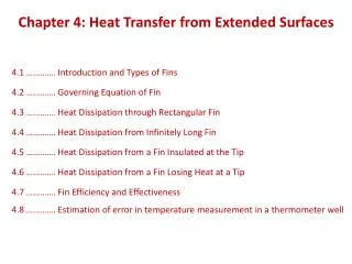
Heat Transfer from Extended Surfaces
900 likes | 2.21k Views
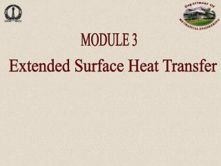
Heat Transfer from Extended Surfaces. Heat Transfer Enhancement by Fins. Bare surface. Finned surface. Typical finned-tube heat exchangers. Straight fin of uniform cross section. Straight fin of nonuniform cross section. Annular fin. Pin fin. A c ( x ). dA s ( x ). dx. dx.

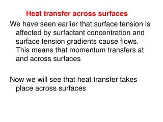
Heat Transfer from Extended Surfaces
E N D
Presentation Transcript
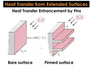
Heat Transfer from Extended Surfaces Heat Transfer Enhancement by Fins Bare surface Finned surface
Straight fin of uniform cross section Straight fin of nonuniform cross section Annular fin Pin fin
Ac(x) dAs(x) dx dx Equation for Extended Surfaces x Tb T∞, h
T(x) T∞, h Ac(x) dAs(x) x dx
P dAs dx Fins of Uniform Cross-Sectional Area L P: fin perimeter Tb Ac(x) = constant, and dAs = Pdx Ac x
where excess temperature: q(x) = T(x) - T∞ L Tb T(x) dx x boundary conditions at x = 0:
L Tb T(x) at x = L: 3 cases dx x 1) very long fin (L → ∞): 2) convection tip: 3) negligible heat loss: adiabatic tip
Temperature distribution 1) long fin: 2) convection tip: 3) adiabatic tip:
or Total heat loss by the fin L 1) long fin: Tb P Ac 2) convection tip: dAs dx x 3) adiabatic tip:
air Example 3.9 • Find: • Temperature distribution T(x) and heat loss qfwhen the fin is constructed from: a) pure copper, b) 2024 aluminum alloy, and c) type AISI 316 stainless steel. • Estimate how long the rods must be for the assumption of infinite length to yield an accurate estimate of the heat loss. • Assumption: • very long fin
Air conductivity at qf Copper: 8.3 W Aluminum alloy: 5.6 W Stainless steel: 1.6 W 1) For a very long fin heat loss: Copper: k = 398 W/m.K Aluminum alloy: k = 180 W/m.K Stainless steel: k = 14 W/m.K
or 2) For the adiabatic condition at the tip qf = MtanhmL (long fin: qf = M) To get an accuracy over 99% Copper: 0.19 m Aluminum alloy: 0.13 m Stainless steel: 0.04 m
T(r) T∞, h
in terms of excess temperature where When k = const, boundary conditions: when an adiabatic tip is presumed
General Solution: where Particular solutions g: real n : real and n : zero or integer and g : imaginary n : fractional and n : zero or integer and Solutions to generalized Bessel equations
Thus, present case: boundary conditions:
Heat loss from the fin T(r) T∞, h
Fin Performance • fin effectiveness • fin resistance • fin efficiency
(rule of a thumb) 1. Fin effectiveness Ac,b: fin cross-sectional area at the base Tb heat loss without fin Ac,b T∞, h fin effectiveness: design criteria: Assume hs are the same for with or without fin.
Ex) long straight fin with uniform cross- sectional area In order to get high fin performance • large k material • installation of fins at the lower h side • thin shape
long fin adia. tip provides upper limit of ef, which is reached as L approaches infinity. Practically qf for the adiabatic tip reaches 98% of heat transfer when mL = 2.3. Thus, the fin length longer than L = 2.3/m is not effective.
2. Fin resistance Tb Ac,b T∞, h qb: driving potential Thermal resistance due to convection at the exposed base: Rt,b
L Tb P Ac dAs dx x 3. Fin efficiency qmax: heat loss when the whole fin is assumed at Tb Ex) straight fin of uniform cross-sectional area with an adiabatic tip
L Tb t D x Errors can be negligible if or For an active tip, the above relation can be used with fin length correction. rectangular fin: pin fin:
When w >> t, P ~ 2w, w t Lc Ap Corrected fin profile area
Efficiency of straight fins (rectangular, triangular, and parabolic profile)
Overall Surface Efficiency single fin efficiency: overall efficiency of array of fins: At : area of fins + exposed portion of the base
Tc In the case of press fit: thermal contact resistance Tb T∞
air Example 3.10 Annual fins Engine cylinder Cross-section (2024 T6 Al alloy) Find: Increase in heat transfer, Dq = qt – qwo, associated with using fins
1) Heat transfer rate H = 0.15 m t = 6 mm hf: known
H = 0.15 m t = 6 mm To get hf, use Fig. 3.19. Parameters: 2024 T6 Al k = 186 at 400 K
0.15 0.95
H = 0.15 m t = 6 mm Without fins The amount of increase in heat transfer
Comments: Fixed fin thickness : 6 mm, Minimum fin gap : 4 mmNmax= H/S =15
Fixed fin gap : 4 mm, Minimum fin thickness : 2 mm Nmax= H/S =25
Example 3.11 Hydrogen-air Proton Exchange Membrane (PEM) fuel cell Without finned heat sink With finned heat sink • Known: • Dimensions of a fuel cell and finned heat sink • Fuel cell operating temperature • Rate of thermal energy generation: 11.25 W • Power production: P = 9 W • Relationship between the convection coefficient and the air channel dimensions
Find: • Net power of the fuel cell-fan system for no heat sink, Pnet = P – Pf • # of fins N needed to reduce the fan power consumption by 50% • Assumptions: • Steady-state conditions • Negligible heat transfer from the edges of the fuel cell, as well as from the front and back faces of the finned heat sink • 1D heat transfer through the heat sink • Adiabatic fin tips • Negligible radiation when the heat sink is in place.
Fan power consumption: P = 9 W Fuel cell 1. Volumetric flow rate of cooling air: The fan consumes more power than is generated by the fuel cell, and the system cannot produce net power.
contact joint (contact) + finned sink base (conduction) + exposed base of finned side (convection) + fins (conv+cond) 2. To reduce the fan power consumption by 50%, Aluminum fined sink: k = 200 W/m.K Lc = 50 mm Thermal circuit = 11.25 W
: 2 sides of the heat sink assembly Aluminum fined sink: k = 200 W/m.K Lc = 50 mm