Extended Surface Heat Transfer
MODULE 3. Extended Surface Heat Transfer. EXTENDED SURFACES / FINS. Convection: Heat transfer between a solid surface and a moving fluid is governed by the Newton’s cooling law: q = hA(T s -T ). Therefore, to increase the convective heat transfer, one can

Extended Surface Heat Transfer
E N D
Presentation Transcript
MODULE 3 Extended Surface Heat Transfer
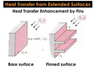
EXTENDED SURFACES / FINS • Convection: Heat transfer between a solid surface and a moving fluid is governed by the Newton’s cooling law: q = hA(Ts-T). Therefore, to increase the convective heat transfer, one can • Increase the temperature difference (Ts-T) between the surface and the fluid. • Increase the convection coefficient h. This can be accomplished by increasing the fluid flow over the surface since h is a function of the flow velocity and the higher the velocity, the higher the h. Example: a cooling fan. • Increase the contact surface area A. Example: a heat sink with fins.
Extended Surface Analysis Tb P: the fin perimeter Ac: the fin cross-sectional area x AC is the cross-sectional area
Extended Surface Analysis (contd...) For example: assume the tip is insulated and no heat transfer d/dx(x=L)=0 The temperature distribution is given by The fin heat transfer rate is given by
Temperature distribution for fins of different configurations
Example • An Aluminum pot is used to boil water as shown below. The handle of the pot is 20-cm long, 3-cm wide, and 0.5-cm thick. The pot is exposed to room air at 25C, and the convection coefficient is 5 W/m2 C. Question: can you touch the handle when the water is boiling? (k for aluminum is 237 W/m C) T = 25 C h = 5 W/ m2 C x 100 C
Example (contd...) We can model the pot handle as an extended surface. Assume that there is no heat transfer at the free end of the handle. The condition matches that specified in the fins Table, case B. Use the following data: h=5 W/ m2 C, P=2W+2t=2(0.03+0.005)=0.07(m), k=237 W/mC, AC=Wt=0.00015(m2), L=0.2(m) Therefore, m=(hP/kAC)1/2=3.138, M=(hPkAC)(Tb-T)=0.111b=0.111(100-25)=8.325(W)
Example (contd…) Plot the temperature distribution along the pot handle As shown in the figure, temperature drops off but not very steeply. This is because k of aluminium is fairly high. At the midpoint, T(0.1)=90.4C. At the end T(0.2)=87.3C. Therefore, it should not be safe to touch the end of the handle. The end condition is insulated, hence the gradient is zero.
Example (contd...) The total heat transfer through the handle can be calculated also. qf=Mtanh(mL)=8.325tanh[(3.138)(0.2)]=4.632 W If a stainless steel handle is used instead, what will happen? For a stainless steel, the thermal conductivity k=15 W/m°C, which is much less compared to aluminium. Using the same process parameter as before:
Example (contd...) Temperature at the handle (x=0.2 m) is only 37.3 °C, not hot at all. This example illustrates the important role of the thermal conductivity of the material in the temperature distribution in a fin.
T Tb Fin Design Total heat loss: qf=Mtanh(mL) for an adiabatic fin, or qf=Mtanh(mLC) if there is convective heat transfer at the tip
Fin Effectiveness How effective a fin can enhance heat transfer is characterized by the fin effectiveness f: Ratio of fin heat transfer and the heat transfer without the fin. For an adiabatic fin:
Fin Effectiveness (contd...) • To increase f, the fin’s material should have higher thermal conductivity, k. • It seems to be counterintuitive that the lower convection coefficient, h, the higher f. But it is not because if h is very high, it is not necessary to enhance heat transfer by adding heat fins. Therefore, heat fins are more effective if h is low. Observation: If fins are to be used on surfaces separating gas and liquid. Fins are usually placed on the gas side. (Why?)
Fin Effectiveness (contd...) • P/AC should be as high as possible. Use a square fin with a dimension of W by W as an example: P=4W, AC=W2, P/AC=(4/W). The smaller W, the higher the P/AC, and the higher f. • Conclusion: It is preferred to use thin and closely spaced (to increase the total number) fins.
Tb x x Fin Efficiency (contd…) For infinite k T(x)=Tb, the heattransfer is maximum T(x)<Tb for heat transfer to take place Ideal heat transfer qmax Total fin heat transfer qf Ideal situation Real situation
Fin Efficiency (cont.) Use an adiabatic rectangular fin as an example:
qf qb Overall Fin Efficiency Overall fin efficiency for an array of fins: Define terms: Ab: base area exposed to coolant Af: surface area of a single fin At: total area including base area and total finned surface, At=Ab+NAf N: total number of fins
Thermal Resistance Concept L1 A=Ab+NAb,f t Rb=t/(kbA) T1 T T1 Tb T2 T R1=L1/(k1A) Tb T2