Download
1 / 58
580 likes | 613 Views
Explore the basic parts and adjustments of film and digital cameras, along with the functioning of the human eye and corrective lenses. Learn about focusing, aperture settings, and overcoming visual impairments with lenses.

E N D
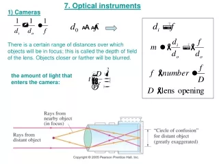
33-5 Cameras: Film and Digital • Basic parts of a camera: • Lens • Light-tight box • Shutter • Film or electronic sensor
33-5 Cameras: Film and Digital • Camera adjustments: • Shutter speed: controls the amount of time light enters the camera. A faster shutter speed makes a sharper picture. • f-stop: controls the maximum opening of the shutter. This allows the right amount of light to enter to properly expose the film, and must be adjusted for external light conditions. • Focusing: this adjusts the position of the lens so that the image is positioned on the film.
33-5 Cameras: Film and Digital Example 33-8: Camera focus. How far must a 50.0-mm-focal-length camera lens be moved from its infinity setting to sharply focus an object 3.00 m away?
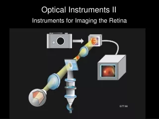
33-6 The Human Eye; Corrective Lenses The human eye resembles a camera in its basic functioning, with an adjustable lens, the iris, and the retina.
33-6 The Human Eye; Corrective Lenses Figure 33-26 goes here. Most of the refraction is done at the surface of the cornea; the lens makes small adjustments to focus at different distances.
33-6 The Human Eye; Corrective Lenses Near point: closest distance at which eye can focus clearly. Normal is about 25 cm. Far point: farthest distance at which object can be seen clearly. Normal is at infinity. Nearsightedness: far point is too close. Farsightedness: near point is too far away.
33-6 The Human Eye; Corrective Lenses Nearsightedness can be corrected with a diverging lens.
33-6 The Human Eye; Corrective Lenses And farsightedness with a diverging lens.
33-6 The Human Eye; Corrective Lenses Example 33-12: Farsighted eye. Sue is farsighted with a near point of 100 cm. Reading glasses must have what lens power so that she can read a newspaper at a distance of 25 cm? Assume the lens is very close to the eye.
33-6 The Human Eye; Corrective Lenses Example 33-13: Nearsighted eye. A nearsighted eye has near and far points of 12 cm and 17 cm, respectively. (a) What lens power is needed for this person to see distant objects clearly, and (b) what then will be the near point? Assume that the lens is 2.0 cm from the eye (typical for eyeglasses).
33-6 The Human Eye; Corrective Lenses Vision is blurry under water because light rays are bent much less than they would be if entering the eye from air. This can be avoided by wearing goggles.
33-7 Magnifying Glass A magnifying glass (simple magnifier) is a converging lens. It allows us to focus on objects closer than the near point, so that they make a larger, and therefore clearer, image on the retina.
33-7 Magnifying Glass The power of a magnifying glass is described by its angular magnification: If the eye is relaxed (N is the near point distance and f the focal length): If the eye is focused at the near point:
33-10 Aberrations of Lenses and Mirrors Spherical aberration: rays far from the lens axis do not focus at the focal point. Solutions: compound-lens systems; use only central part of lens.
33-10 Aberrations of Lenses and Mirrors Distortion: caused by variation in magnification with distance from the lens. Barrel and pincushion distortion:
33-10 Aberrations of Lenses and Mirrors Chromatic aberration: light of different wavelengths has different indices of refraction and focuses at different points.
33-10 Aberrations of Lenses and Mirrors Solution: Achromatic doublet, made of lenses of two different materials
Summary of Chapter 33 • Lens uses refraction to form real or virtual image. • Converging lens: rays converge at focal point. • Diverging lens: rays appear to diverge from focal point. • Power is given in diopters (m-1):
Summary of Chapter 33 • Thin lens equation: • Magnification:
Summary of Chapter 33 • Camera focuses image on film or electronic sensor; lens can be moved and size of opening adjusted (f-stop). • Human eye also makes adjustments, by changing shape of lens and size of pupil. • Nearsighted eye is corrected by diverging lens. • Farsighted eye is corrected by converging lens.
Summary of Chapter 33 • Magnification of simple magnifier: • Telescope: objective lens or mirror plus eyepiece lens. Magnification:
Units of Chapter 34 • Waves versus Particles; Huygens’ Principle and Diffraction • Huygens’ Principle and the Law of Refraction • Interference – Young’s Double-Slit Experiment • Intensity in the Double-Slit Interference Pattern • Interference in Thin Films • Michelson Interferometer • Luminous Intensity
34-1 Waves versus Particles; Huygens’ Principle and Diffraction Huygens’ principle: every point on a wave front acts as a point source; the wave front as it develops is tangent to all the wavelets.
34-1 Waves versus Particles; Huygens’ Principle and Diffraction Huygens’ principle is consistent with diffraction:
34-2 Huygens’ Principle and the Law of Refraction Huygens’ principle can also explain the law of refraction. As the wavelets propagate from each point, they propagate more slowly in the medium of higher index of refraction. This leads to a bend in the wave front and therefore in the ray.
34-2 Huygens’ Principle and the Law of Refraction The frequency of the light does not change, but the wavelength does as it travels into a new medium:
34-2 Huygens’ Principle and the Law of Refraction Highway mirages are due to a gradually changing index of refraction in heated air.
34-3 Interference – Young’s Double-Slit Experiment If light is a wave, interference effects will be seen, where one part of a wave front can interact with another part. One way to study this is to do a double-slit experiment:
34-3 Interference – Young’s Double-Slit Experiment If light is a wave, there should be an interference pattern.
1) 2) 3) 4) A ConcepTest 34.1Superposition B If waves A and B are superposed (that is, their amplitudes are added) the resultant wave is
1) 2) 3) 4) A ConcepTest 34.1Superposition B If waves A and B are superposed (that is, their amplitudes are added) the resultant wave is The amplitudes of waves A and B have to be added at each point!
34-3 Interference – Young’s Double-Slit Experiment The interference occurs because each point on the screen is not the same distance from both slits. Depending on the path length difference, the wave can interfere constructively (bright spot) or destructively (dark spot).
34-3 Interference – Young’s Double-Slit Experiment We can use geometry to find the conditions for constructive and destructive interference: and
34-3 Interference – Young’s Double-Slit Experiment Between the maxima and the minima, the interference varies smoothly.
34-3 Interference – Young’s Double-Slit Experiment Conceptual Example 34-1: Interference pattern lines. (a) Will there be an infinite number of points on the viewing screen where constructive and destructive interference occur, or only a finite number of points? (b) Are neighboring points of constructive interference uniformly spaced, or is the spacing between neighboring points of constructive interference not uniform?
34-3 Interference – Young’s Double-Slit Experiment Example 34-2: Line spacing for double-slit interference. A screen containing two slits 0.100 mm apart is 1.20 m from the viewing screen. Light of wavelength λ = 500 nm falls on the slits from a distant source. Approximately how far apart will adjacent bright interference fringes be on the screen?
34-3 Interference – Young’s Double-Slit Experiment Conceptual Example 34-3: Changing the wavelength. (a) What happens to the interference pattern in the previous example if the incident light (500 nm) is replaced by light of wavelength 700 nm? (b) What happens instead if the wavelength stays at 500 nm but the slits are moved farther apart?
34-3 Interference – Young’s Double-Slit Experiment Since the position of the maxima (except the central one) depends on wavelength, the first- and higher-order fringes contain a spectrum of colors.
34-4 Intensity in the Double-Slit Interference Pattern The electric fields at the point P from the two slits are given by . where
34-4 Intensity in the Double-Slit Interference Pattern The two waves can be added using phasors, to take the phase difference into account:
34-4 Intensity in the Double-Slit Interference Pattern The time-averaged intensity is proportional to the square of the field:
34-4 Intensity in the Double-Slit Interference Pattern This plot shows the intensity as a function of angle.
34-4 Intensity in the Double-Slit Interference Pattern Example 34-5: Antenna intensity. Two radio antennas are located close to each other, separated by a distance d. The antennas radiate in phase with each other, emitting waves of intensity I0 at wavelength λ. (a) Calculate the net intensity as a function of θ for points very far from the antennas. (b) For d = λ, determine I and find in which directions I is a maximum and a minimum. (c) Repeat part (b) when d = λ/2.
ConcepTest 34.3a Double Slits I 1) spreads out 2) stays the same 3) shrinks together 4) disappears In a double-slit experiment, when the wavelength of the light is increased, the interference pattern
ConcepTest 34.3a Double Slits I 1) spreads out 2) stays the same 3) shrinks together 4) disappears In a double-slit experiment, when the wavelength of the light is increased, the interference pattern d sin = m If is increased and d does not change, then must increase, so the pattern spreads out.
34-5 Interference in Thin Films Another way path lengths can differ, and waves interfere, is if they travel through different media. If there is a very thin film of material – a few wavelengths thick – light will reflect from both the bottom and the top of the layer, causing interference. This can be seen in soap bubbles and oil slicks.
34-5 Interference in Thin Films The wavelength of the light will be different in the oil and the air, and the reflections at points A and B may or may not involve phase changes.