Download
1 / 15
170 likes | 463 Views
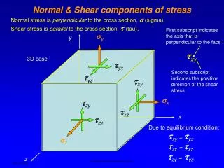
First subscript indicates the axis that is perpendicular to the face. y. y. xy. 3D case. yx. Second subscript indicates the positive direction of the shear stress. yz. xy. x. zy. xz. x. zx. Due to equilibrium condition;. z. xy =. yx. zx =. xz. zy =.

E N D
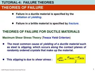
First subscript indicates the axis that is perpendicular to the face y y xy 3D case yx Second subscript indicates the positive direction of the shear stress yz xy x zy xz x zx Due to equilibrium condition; z xy= yx zx= xz zy= yz z Normal & Shear components of stress Normal stress is perpendicular to the cross section, (sigma). Shear stress is parallel to the cross section, (tau). Mechanical Engineering Department
xy x Normal & Shear components of stressTwo Dimensional Case y xy x xy xy y Mechanical Engineering Department
Normal Stress Due to Axial Load A positive sign is used to indicate a tensile stress (tension), a negative sign to indicate a compressive stress (compression) Uniform stress distribution across the cross sectional area Mechanical Engineering Department
Direct Shear Direct shear is produced where there is no bending (or stress caused by bending is negligible Mechanical Engineering Department
Stress distribution Maximum stress at the surface Where I is area moment of inertia I = π (d)4 / 64 (round cross section) Normal Stress Due to Bending Load Typical loads on a barbell Mechanical Engineering Department
Transverse Shear In beam loading, both bending stress and shear stress due to transverse loading are applied to particular section. Maximum shear stress due to bending Mechanical Engineering Department
Stress distribution Maximum shear stress at the surface Where J is polar area moment of inertia J = π (d)4 / 32 (round cross section) Shear Stress Due to Torque (twisting) Torsional stress is caused by twisting a member Mechanical Engineering Department
Power transmission Mixer Torsional Stress - examples Structural member Mechanical Engineering Department
Power transmission, bending and torsion stresses Billboards and traffic signs, bending, axial and torsion stresses Trailer hitch, bending and axial stresses Combined Stresses - examples Bicycle pedal arm and lug wrench, bending and torsion stresses Mechanical Engineering Department
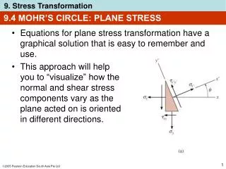
1, 2=(x + y)/2± [(x - y)/2]2 + (xy)2 3 - (x+ y + z) 2 + (x y + x z+ y z - xy - xz - yz) - (x y z - 2xy xz yz - x yz- y xz- z xy) = 0 2 2 2 2 2 2 The three non-imaginary roots are the principal stresses 2D Case 1 > 2 Principal Stresses – Mohr’s Circle 3D Case 1 > 2> 3 Mechanical Engineering Department
3D Case ′ = (1+ 2 + 3 - 12 - 13 - 23)1/2 2 2 2 3= 0 2D Case, Substituting for 1, 2 from Mohr circle, we have the von Mises stress in terms of component stresses. ′ = (x+ y - xy + 3xy)1/2 ′ = (x+ 3xy)1/2 ′ = (1+ 2 - 12)1/2 2 2 2 2 2 2 2 In most cases y= 0 Equivalent Stress - von Mises Stress Using the distortion energy theory, a single equivalent or effective stress can be obtained for the entire general state of stress given by 1,2 and 3. This equivalent (effective) stress can be used in design and is called von Mises stress (′). Mechanical Engineering Department
13 12 23 Maximum Shear Stress – Mohr’s Circle Mohr’s circles for a 3D case 3 2 1 max = largest of the three shear stresses, in this case 13 Mechanical Engineering Department
1 and 2 have the opposite sign. 13 12 12 23 23 13 2 3=0 1 1 1 - 2 max=12= max=13 = 2 2 Maximum Shear Stress – Mohr’s Circle Mohr’s circles for a 2D case 1 and 2 have the same sign, both positive or negative. 2 1 3=0 Mechanical Engineering Department
εy Strain in the y direction v = = εx Strain in the x direction y x Uniaxial state of stress z x εx = x x E = - v εx = - v εx εy εz Stress – Strain Relationship Load Poisson’s Ratio, v Mechanical Engineering Department
x y z y y x x x z y = v εx v εy v v v v v E E E E E E E E E E = v εy v εx εz = y x y z x Triaxial state of stress y εy εx εy εz εx = = = = = z E E E E E v x x v z v y Stress – Strain Relationship Biaxial state of stress Strain in the x direction due to the force in the y direction y x x y Mechanical Engineering Department