Download
1 / 28
310 likes | 641 Views
Characterization of the Hamamatsu R8900-M16 Multianode Photomultiplier Tube (PMT). Paul Mekhedjian Department of Physics University of California, Santa Cruz Department of Energy – INFN Summer 2007 Studentship. Why do we care? High granularity Pb-Sci Fibers calorimeter. KLOE readout

E N D
Characterization of the Hamamatsu R8900-M16 Multianode Photomultiplier Tube (PMT) Paul Mekhedjian Department of Physics University of California, Santa Cruz Department of Energy – INFN Summer 2007 Studentship
Why do we care?High granularity Pb-Sci Fibers calorimeter • KLOE readout • 4.4 x 4.4 cm2 read by photomultipliers • 1 module 52x25 cm2 read by 60 photomultipliers. • Increasing granularity by a factor 16 using HAMAMATSU photomultipliers. • Better particle identification • Less merging probability for pair of clusters • Useful for neutron detection.
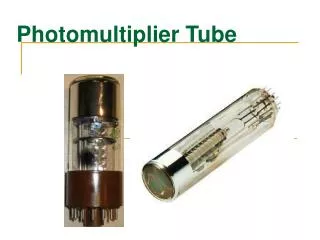
Device Aspect Hamamatsu R8900-M16 Window material: Borosilicate glass Arrangement and Type: 4 x 4 grid Number of channels: 16 (each 5.7x5.7mm2) Effective Window Area: 23.5x23.5mm2 Photocathode material: Bialkali Spectral response range: 300 to 650 nm Compact form and design practical for assembly and use in calorimeters!
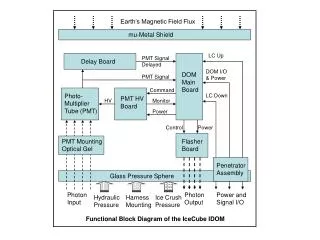
Signal formation process: Device scheme: • Photons strike photocathode • Electrons are produced via photoelectric effect and directed to the first dynode past the focusing mesh • The dynodes are made of materials with very low bandgap energies, which produce additional electrons upon collision • Electrons are directed and oriented from the photocathode to the multianode by a simple electric field generated by the dynodes • The signal is finally collected at the anode and its gain is dependent on the total number of dynodes and the applied voltage. 16 anodes signal Connector Socket 12 (last dynode signal output)
Analog Circuit Amplification Each anode/DY12 output can be connected by a LEMO cable to the oscilloscope Amplifier Circuit: Connector socket
Summary of Talk • Quality of Lunch?! • Linearity of response • Signal shape(Rise Time, Fall Time, Full Width at Half Maximum “FWHM”) • Transit Time & Transit Time Spread • Relative Gain vs. High Voltage • Response in Channel Homogeneity • Channel-Channel Crosstalk
Apparatus & Setup Oscilloscope Low Voltage Power Supply for Analog Amplifiers 50Ω Terminator Laser Pulse 2D Micrometer Slide PMT Input Socket Laser Control Unit High Voltage Power Supply Laser / Photon Source
A Typical Signal • This is what a typical signal would look like on the oscilloscope once the high voltage power was turned on.
Signal on the oscilloscope From a single anode… Rise time: Time from 10% to 90% of the signal amplitude Fall time: Time from 90% to 10% of the signal amplitude Area (integral) of the signal is proportional to the collected charge at a particular anode
What does this dial do? Prior to crosstalk measurements, we discovered that varying the dial amplitude gives interesting results…
Amplitude Response The signal response of the photomultiplier tube is linear for a certain range of the laser’s dial amplitude. It then enters a breakdown region (past ~900) where the trend follows an exponential or asymptotic behaviour.
Charge Response The response for the channel’s charge on the anode follows a nearly identical trend!
Linearity of Both Amplitude and Charge a = 2.73 +/- 0.01mV b = -13 +/- 8mV a = 0.0093 +/- 0.0001 nV*s b = 0.751 +/- 0.075 nV*s • After investigating only the dial range of 500 to 850, we have found the linear response region.
Charge Offset • a = 0.0093 +/- 0.0001 nV*s • b = 0.751 +/- 0.075 nV*s • y = 0.0093*x + 0.751 (i.e. Charge = 0.0093*Amplitude + 0.751) • It should be noted that the parameters of the linear fit produce a constant which has physical meaning. • We know that if a light source has no amplitude, the photomultiplier tube cannot produce a value of charge. • Thus, based on the fit, there is a charge offset (given by the parameter b. This parameter will be useful in future slides…
Signal shape vs amplitude Slope: 0.026ns/mV It should be noted that some signal properties vary more than others with an increase in amplitude. Slope: 0.008ns/mV Slope: 0.003ns/mV It is important for the uniformity of the calorimeter response with respect to particles of different energy that the signal shape is independent (more or less) from the signal amplitude.
Transit Time Shift So honestly… How long does it take from a photon to leave the laser, hit the photocathode, photomultiply, and then leave the PMT from the anode? The time transit is what this quantity is known as and we wished to see how much this quantity differed from channel to channel… This plot illustrates how other channels deviate from a reference channel (shown as a white box without a number). This is crucial because it affects the time resolution of a potential KLOE calorimeter upgrade with multianode PMTs.
Charge Characteristics • Since charge is collected at the anode, it is interesting to see how this charge fluctuates. • We can also use this information to study a quantity known as TTS (time transit spread) as a function of the number of photoelectrons (sQ/Q). This is where one may use the charge offset previously mentioned to further analyze raw values of photoelectrons which hit the photocathode in the first place.
Relative Gain of PMT Channels • Hamamatsu documentation suggests gain might not be completely homogenous from channel to channel • We wished to verify this premise experimentally with our apparatus. • Here, relative gain means that we are normalizing to the data obtained at 500V for each channel and does not represent an absolute quantity.
Total Channel Relative Gain • In this measurement, we had the laser incident on a particular channel and took the charge collected by the total channel (DY12). • This process was repeated for each channel and its gain represented by a slope in a linear model, the same process shown in the previous slide.
Channel Homogeneity for Socrates • We also wanted to test how homogeneous channels were. • Below are plots of Socrates, the first PMT we tested this summer. Charge Homoegeneity : Amplitude Homogeneity:
Channel Homogeneity for Nietzsche • Below are plots of Nietzsche, the eighth PMT we tested this summer. Charge Homoegeneity : Amplitude Homogeneity:
Making Sense of Chaos FWHM*10-7 s • Fact: After many days without food and water, you can be convinced that 2+2=5. Similarly, we can do the same things with these plots. • What we need in our data is a definitive pattern so we can say that “Yes, this happens due to this or that. “ • Then we made the FWHM histogram for Socrates and discovered some order… • We hope that we can discover additional photomultiplier characteristics to make similar conclusions.
Crosstalk Measurements • The crosstalk is the response of a given channel when a different channel is fired upon by the laser beam. • In the ideal case the channels are completely decoupled but in reality a small correlation is observed. High crosstalk could potentially spoil the resolution power of the device. Amplitude Crosstalk: Charge Crosstalk:
Alternate representation… • Three dimensions help to illustrate how much more profound an effect amplitude has in interchannel communication. • Charge collection is a more important quantity for the KLOE calorimeter because as an integral quantity, it has the ability to cancel out positive and negative noise to leave only real information, whereas amplitude includes background noise. Charge Crosstalk: Amplitude Crosstalk:
Results and Conclusions • Crosstalk measurements verify that only channels juxtaposed with the incident channel express crosstalk that could be dangerous in experimental settings. • Presented in the former slide are the results for only one PMT. We measured eleven in total, but would need a full day to show them all in depth. • The data we have collected will be very useful in preparation for the initialization of the experiment in Frascati.
E poi? • Adesso…We hope to see how well the KLOE calorimeter will work with its array of PMTs. • The granularity of the multi-anode PMTs should invaluably assist in more precise results with respect to determining position of photons incident on the tubes. • More investigation on definite correlation and studying of FWHM, the most predictable reading we have seen so far.
Thanks! • Gratitude goes to INFN, Universita di Roma III and also to everyone who has welcomed me here! • Special thanks to Filippo Ceradini, Paolo Branchini, and Biagio Di Micco for assisting me with my work. Grazie milioni!