Download
1 / 13
130 likes | 305 Views
The characteri stics of the MA-PMT HAMAMATSU : H8711-10 for the MINICAL. Samuel Kazarian, Volker Korbel, Pavel Murin, Stefan Valkar, Jan Weichert.

E N D
The characteristics of the MA-PMT HAMAMATSU : H8711-10 for the MINICAL Samuel Kazarian, Volker Korbel, Pavel Murin, Stefan Valkar, Jan Weichert
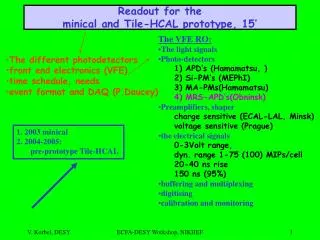
Before construction of the 1 m3 prototype of HCAL ( TILECAL and DIGICAL versions ) a small calorimeter with 29 scintillator layers has been built by Prague labs. MINICAL with dimensions 21x21x825 cm consists from 30 stainless steel absorber plates. Two perpendicular side plates ( 3 mm thick ) with the precise 5mm holes hold the absorber plates in vertical or horizontal positions and guarantee 7.5mm gaps for the scintillator tiles, which are fixed to 0.4 mm SS support plates. 8 absorber plates were constructed as glued sandwich from 5 mm thick SS (316 Ti ) plates. The mean thickness of the glued absorbers was 20.2 mm, (~20.5 mm for the homogeneous absorbers).The MINICAL test array will be equipped with up to 165 individual tile-fiber elements ( or 55 cells 3 tiles each ). At the beginning 4 HAMAMATSU multianode PMs with the 16 anodes will be used for the readout . New types ( H8711-10) with very low cross talk were tested in DESY using H1 test setup which was built for the ROMAN POT collaboration.
Later they will be replaced by two 32 channel ( 4x8 ) Si-APD matrix arrays HAMAMATSU S8550 and/or Si-PMs from the development carried out by russian institutes. For the new MA-PMTs holders and masks with the 16 holes ( 1 or 2.1 mm diameter) were produced, and installed into black box. The light pulses generated by blue LED HLMP CB30 ( 470 nm ) were directed through clear fiber ( 0.5 mm diameter ) towards center of each fotocathode. The response of 16 channels were monitored by charge sensitive ADC (LeCroy-2249A). The measured results are illustrated by tables 1-3 and figures 1-2.
Conclusions • The MINICAL frame together with light-tight box and connectors for 64 electronics channels was built and now is available at the DESY test beam. • The new MA-PMTs, HAMAMATSU H8711-10 with low cross-talk ( < 5% ) has been equipped with new masks and connectors. The data collected with H1 (roman pot) test setup confirm the results on anode uniformity and cross-talk obtained by HAMAMATSU. • The large variation of the gain for 16 channels 40 < Gi < 100 % is making the task of the response equalization for all channels rather difficult.
1 0.59 2 1.98 3 0.79 4 0.40 5 1.58 6 100.00 7 0.79 8 0.20 9 0.20 10 1.78 11 0.20 12 -0.20 13 0.00 14 0.00 15 0.00 16 0.00 Table 1. X-talk distribution for channel #6, (HV=850V) in % after Pedestals subtraction. Negative X-talk in #12 is a consequence of pedestal variation.
1 0.002 0.003 2.564 -2.56 5 7.696 100.00 7 5.138 -5.13 9-5.1310 -2.5611 -2.5612 -2.56 130.00 14 0.00 15 0.00 16 0.00 Table 2. X-talk distribution for channel #6, (HV=600V) in % after Pedestals subtraction. Negative X-talk in #12 is a consequence of pedestal variation.
Figures 1. Amplitude (after pedestal subtraction) of fired channel #6 together with the response of the remaining channels. The small Amplitudes closed to 0 (detail on the right picture) represent X-talk from #6 to the rest channels.
Figure 2. The HV dependence of the X-talk with all channels included. Small X-talk (< 5 %) is not measurable with good precision for low HV (Signal Amplitude is close to Pedestal)
Figures 2a+ cells for ch#6 are (#2#5#7#10), X cells are (#1#3#9#11) represent X-talk from #6 to the rest channels.
U=850V: 1 63. 257. 3 58. 4 64. U=750V: 59. 53. 54. 60. U=600V: 49. 42. 44. 45. U=850V: 5 66. 6 64. 7 66. 8 67. U=750V: 63. 61. 61. 59. U=600V: 68. 55. 52. 54. U=850V: 9 78. 10 100. 11 85. 12 77. U=750V: 74. 100. 82. 74. U=600V: 75. 100. 83. 69. U=850V: 13 91. 14 99. 15 87. 16 77. U=750V: 91. 96. 85. 75. U=600V: 90. 87. 86. 76. Table 3. Anode Uniformity after Pedestal subtraction. Light Source: 0.5 mm clear fiber fired by Blue LED (470nm) positioned in the center of each Photocathode