State Machine Design
330 likes | 739 Views
State Machine Design. State Machine Design. This presentation will Define a state machine and Illustrate the block diagram for a state machine . Provide several examples of everyday items that are controlled by state machines. Describe the steps in the state machine design process.

State Machine Design
E N D
Presentation Transcript
State Machine Design • This presentation will • Define a state machine and Illustrate the block diagram for a state machine. • Provide several examples of everyday items that are controlled by state machines. • Describe the steps in the state machine design process. • Provide an example of a state machine design.
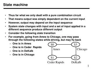
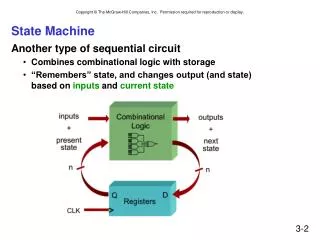
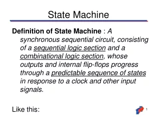
State Machine A synchronous sequential circuit, consisting of a sequential logic section and a combinational logic section, whose outputs and internal flip-flops progress through a predictable sequence of states in response to a clock and other input signals. Input Combo Logic Memory Flip-Flops Output Combo Logic Output(s) Input(s) Clock
Parts of a State Machine • Input Combinational Logic • Memory • Output Combinational Logic Input Combo Logic Memory Flip-Flops Output Combo Logic Output(s) Input(s) Clock
Input Combinational Logic What should happen next based on the buttons, switches, and other inputs? Input Combo Logic Memory Flip-Flops Output Combo Logic Output(s) Input(s) Clock
Memory Flip-Flops determine the number of states in the design and trigger the state transitions based on the inputs. Input Combo Logic Memory Flip-Flops Output Combo Logic Output(s) Input(s) Clock
Output Combinational Logic What should motors, indicators, and other outputs do once the flip-flops have caused the transition to a new state? Input Combo Logic Memory Flip-Flops Output Combo Logic Output(s) Input(s) Clock
Examples of State Machines Many everyday devices are controlled by state machines. Traffic Lights Garage Door Numeric Keypads Vending Machines
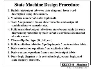
State Machine Design • Create a State Graph • Determine the number of States and label • Determine the number of State Variables and label (How many flip-flops needed?) • Label Outputs and Encode Outputs to States • Create State Transition Table from the State Graph • Write and Simplify Design Equations from the State Transition Table • Design Circuit
State Graphs A state graph shows the sequence of states that the state machine will transition to on each clock transition. This is an example of a state graph with four states (S0-S3).
State Graphs Each state “bubble” is labeled (S0,S1,S2,S3). These labels are arbitrary. Each transition arc is labeled with the values of the input variables that make the transition occur.
Anatomy of a State Graph Transition Arc (For Input X=0) Hold State Input Variable (X) X = 0 S0 State (S0) State “Bubble” Qa Qb 0 0 Y=0 & Z=1 X = 1 Transition Arc (For Input X=1) Next State State Variables (Qa & Qb) Next State “Bubble” Output Variables (Y & Z)
State Variables S0 The state variables are actually the outputs of the memory flip-flops. For that reason they are typically labeled Qa, Qb, etc. Qa Qb 0 0 This four state example would require (2) flip-flip (Qa and Qb) to clock through four states (S0-S3). 1st State (SO) Qa Qb = 0 0 2nd State (S1) Qa Qb = 0 1 3rd State (S2) Qa Qb = 1 0 4th State (S3) Qa Qb = 1 1
State Variables If a 5th state was needed: Can you guess how many flip-flops and state variables you would need? (It is not possible to have exactly 5 states) How many states would go un-used? 1st State (SO) Qa Qb = 0 0 2nd State (S1) Qa Qb = 0 1 3rd State (S2) Qa Qb = 1 1 4th State (S3) Qa Qb = 1 1 5th Sate (S4) ??????? = ?????
Output Variables Each state “bubble” is assigned output variables. This example has 4 output variables based on what state it is in.
State Transition Tables State Transition Tables are then created from the State Graph. They describe the Present State (inputs) and the Next State (outputs) associated with each state (S0-S3).
State Transition Tables Notice that each state occupies 2 lines on the State Transition Table. That is because (in this example) each transition is triggered by only one of 4 possible inputs at any time. For: Input that causes transition: S0 OS = 0 ;OS = 1 S1 OL = 0 ;OS = 1 S2 CS = 0 ;CS =1 S3 CL = 0 ;CL = 1
State Transition Tables In a state machine, the Next State is actually the output from the Memory flip-flops (Qa* Qb*) when an input is changed. Qa* = Da for the next state on one flip-flop and Qb* = Db for the next state on the other flip-flop
State Transition Tables The outputs from the Memory flip-flops are linked to the Input Combinational Logic. That way a transition is made on the next clock signal to the next state. Qa* = Da for the next state on one flip-flop and Qb* = Db for the next state on the other flip-flop Input Combo Logic Memory Flip-Flops Output Combo Logic Output(s) Input(s) Clock
Design Equations From the State Transition Table you can now determine the un-simplified expressions for the: Input Combinational Logic Da=Qa* Db=Qb* Output Combinational Logic This example has (4) outputs MO – Motor Open Signal MC – Motor Close Signal GO – Gate Open Indicator GC – Gate Closed Indicator
State Machine Design Example • Design a state machine that will count out the last four digits of a phone number ONLY when an Enable pushbutton is pressed. The output should hold the last number until the Enable button is pressed again. (Example 585-476-4691) • Whenever the Enable is a logic (1), the outputs will continuously cycle through the four values 4,6,9,1. Whenever the Enable is a logic (0), the outputs will hold at their current values. • For this design any form of combinational logic may be used, but the sequential logic must be limited to D flip-flops. “4” “6” “9” “1” C3 C2 C1 C0 Phone Numbers Enable Clock
Step 1: Create State Graph (# of States?) EN = 0 S0 EN = 1 EN = 1 “4” S1 S3 EN = 0 EN = 0 “6” “1” S2 “9” EN = 1 EN = 1 EN = 0
Step 2: Determine # of State Variables and Assign EN = 0 S0 EN = 1 EN = 1 Qa Qb 0 0 “4” S1 S3 EN = 0 EN = 0 Qa Qb 0 1 “6” Qa Qb 1 1 “1” S2 Qa Qb 1 0 “9” EN = 1 EN = 1 EN = 0
Step 3: Encode Outputs to States (# Displayed?) EN = 0 S0 EN = 1 EN = 1 Qa Qb 0 0 “4” 0100 C3=0 C2=1 C1=0 C0=0 S1 S3 EN = 0 EN = 0 Qa Qb 0 1 “6” Qa Qb 1 1 “1” 1001 C3=1 C2=0 C1=0 C0=1 0001 C3=0 C2=0 C1=0 C0=1 0110 C3=0 C2=1 C1=1 C0=0 S2 Qa Qb 1 0 “9” EN = 1 EN = 1 EN = 0
Step 4: Create State Transition Table See Slide Notes for a detailed description
Step 6: Circuit Design – AOI Simplified Can you think of a better way to impliment the logic for Db ?