Understanding State Machines: Transitions, Inputs, and Truth Tables
This text discusses the theory behind state machines and the principles of state transitions. It describes how outputs depend not only on current inputs but also on the sequence of inputs, emphasizing the importance of representing states with binary variables. The explanation includes truth tables, state transition diagrams, and the roles of time and clock signals in state changes. Moreover, it outlines the steps in designing a state machine, including the development of state diagrams, tables, and the complex nature of state assignments.

Understanding State Machines: Transitions, Inputs, and Truth Tables
E N D
Presentation Transcript
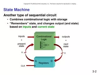
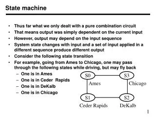
S0 S3 Ames Chicago S1 S2 Ceder Rapids DeKalb State machine • Thus far what we only dealt with a pure combination circuit • That means output was simply dependent on the current input • However, output may depend on the input sequence • System state changes with input and a set of input applied in a different sequence produce different output • Consider the following state transition • For example, going from Ames to Chicago, one may pass through the following states while driving, but may fly back • One is in Ames • One is in Ceder Rapids • One is in DeKalb • One is in Chicago
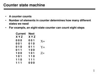
Truth tables to represent state transitions • States can be coded as binary combinations of variables • Each state is represented by n=log N bits • N is total number of states • 2 bits will represent 4 state, 3 bits will represent eight, and so on • For 4 states we use two bits X and Y • A truth table will then give the next state • Xn and Yn can be specified in terms Xo and Yo xn = xo’ yo + xo yo’ yn = xo’ yo’ + xo yo’ = yo’
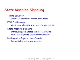
S0 S3 Ames Chicago S1 S2 Ceder Rapids DeKalb State Change, with clock and/or input • In a state transition diagram, state may change with time • A clock signal represents passage of time • Each time a clock arrives, state changes to next state • There is no other explicit input (or there is an implicit input) • There may be an explicit input, say i • Next state may depend on current state and the value of input • Let us assume a binary input • Thus i can be 0 or 1 • The state changes are shown 0 1 1 0 0 1 1 0
Truth tables with input for state transitions • States transition table will have two sets of inputs • Current state variable and input variables • Total number of row in table is 2(n+m) • n is number of variables representing states • m is number of input variables xn=xo’ yo’ i+xo’ yo i’+xo’ yo i+xo yo’ i’ =xo’ i + xo’ yo + xo yo’ i’ yn=xo’ yo’ i’+xo’ yo i+xo yo’ i’+xo yo i = yo’ i’ + yo i
Determining number of states • Identify how many different things we need to keep track of • This is critical to know • Otherwise the number of states (and their meaning) may get out of hand very quickly • This is different than what is the output of interest (in each state we may have some outputs) • For example, if we are to process a sequence of inputs • Depending on interest, the number of states may be different • If we need to know how many 1’s are there, we need states corresponding to count • If we need to know if we have even or odd number of 1’s, we may need only two states
Steps in designing a state machine • Start writing a state diagram • It has an initial state • It has other states to keep track of various activities • Generate a state table • Generate state table in binary • Needs state assignment, i.e., what state will have what code • State assignment is a complex process • For the time being assume straightforward combinations • Derive canonical sum-of-products form equations • You can simplify the equations • When the next state depend upon the inputs, the inputs are examined at the clock ticks