Download
1 / 14
140 likes | 266 Views
Parametric Thermal-Hydraulic Analysis of TBM Primary Helium Loop. Greg Sviatoslavsky Fusion Technology Institute, University of Wisconsin, Madison, WI With contributions from C.P.C. Wong, General Atomics, M. Dagher, S. Smolentsev, UCLA, S. Malang, Consultant, Germany

E N D
Parametric Thermal-Hydraulic Analysis of TBM Primary Helium Loop Greg Sviatoslavsky Fusion Technology Institute, University of Wisconsin, Madison, WI With contributions from C.P.C. Wong, General Atomics, M. Dagher, S. Smolentsev, UCLA, S. Malang, Consultant, Germany ITER US TBM Meeting UCLA MAY 10, 2006
Presentation Outline • Primary helium loop description • First Wall thermal analysis • TBM pressure drop • Results summary • Future work & consideration
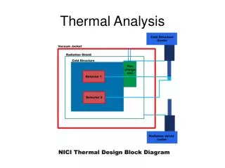
Primary Helium Loop Top Plate He Circuit 2 Grid Plates Back Plate First Wall Divider Plate He Circuit 1 Bottom Plate
First Wall Analysis Approach FW Temperature Limits D-T Transient Thermal Conditions Require Heat Transfer Coefficient (h) Channel Dimensions & Roughening Require Helium Flow Rate Parametric Analysis Helium Inlet & Outlet Temperature Parametric Analysis Max FW Temperature FW Pressure Drop Parametric Analysis FW Channel Layout
First Wall Analysis Input Parameters • 0.3 MW/m2 flux over 90% & 0.5 MW flux over 10% FW • Nuclear heating based on scaling prior neutronic results • 520o C maximum FW temperature at 2 mm depth • 550o C maximum FW surface temperature • 300o C helium TBM inlet temperature • 390o C helium TBM outlet temperature • 20 mm x 19.6 mm channel cross-section dimensions • Uniform sand-grain roughness • Seven pass circuit layout (5 channels per pass)
First Wall Thermal Analysis Results • 0.89 kg/s required helium flow rate • 4813 W/m2-K heat transfer coefficient • 378o C FW helium exit temperature • 523o C maximum FW temperature at 2 mm depth • 556o C maximum FW surface temperature
TBM Pressure Drop Results Top Plate 0.001 MPa Circuit 2 Total P-drop 0.0107 MPa First Wall 0.096 MPa Grid Plates 0.003 MPa 0.01 MPa Divider Plate Circuit 1 Total P-drop 0.104 MPa 0.005 MPa First Wall 0.096 MPa Bottom Plate 0.001 MPa
TBM Pressure Drop Results • First Wall 0.096 MPa • Top/Bottom Plate 0.001 MPa • Divider Plate 0.005 MPa • Upper Grid Plates 0.003 MPa • Lower Grid Plates 0.01 MPa Lower Grid Plate First Wall Upper Grid Plate Divider Plate Bottom Plate Top Plate
Alternate FW Channel Configuration • Downstream (hotter) FW flow requires higher h than upstream (cooler) flow • Control velocity with number of channels per pass [h is f(velocity)] • Initial analysis indicates pressure drop improves by 34% Fixed Flow Rate Pass 1 Pass 2 Pass 3
Future Work & Consideration • Evaluate back plate design • Can we do without 2D roughening? • Determine maximum allowable pressure drop • Investigate alternate configurations • CFD analysis required to better account for FW counter flow and TBM flow distribution • Continue iteration with MHD analysis
Nuclear Heating Values Top Plate 5253 W Grid Plates 17113 W First Wall 82187 W Side Walls 35938 W Divider Plate 12200 W Bottom Plate 5253 W