Download
1 / 12
120 likes | 268 Views
Task 2.3 Thermal-hydraulic analysis of the LFR and ETDR. Konstantin Mikityuk Paul Scherrer Institut. Task 2.3 Thermal-hydraulic analysis of the LFR and ETDR ( PSI , CIRTEN, NRG, SRS,UJV).

E N D
Task 2.3 Thermal-hydraulic analysis of the LFR and ETDR Konstantin MikityukPaul Scherrer Institut
Task 2.3 Thermal-hydraulic analysis of the LFR and ETDR (PSI, CIRTEN, NRG, SRS,UJV) Goal: to assess thermal-hydraulic core performance for the defined core geometry and power distributions provided by task 2.1 and 2.2. The results will be feed-backed to the mentioned task in order to avoid hot spots in the core (cladding and fuel) and to allow a satisfying natural circulation in case of loss of flow. Technical Documents T56 : Thermal-hydraulics assessment of the ETDR core (M24: April 2012) T62 : Thermal-hydraulics assessment of the LFR cores (M30: Oct 2012)
T56: Table of Content 1 INTRODUCTION (PSI) 3 2 1D THERMAL-HYDRAULIC ANALYSIS OF THE CORE (PSI) 6 2.1 1D CORE MODEL 6 2.2 POWER DISTRIBUTION AND COOLING GROUPS 6 3 CFD ASSESSMENT OF GRID SPACER DESIGNS (NRG) 10 3.1 EFIT SPACER DESIGN 10 3.2 SRS SPACER DESIGN 17 3.3 COMPARISON: EFIT SPACER VS. SRS SPACER 23 3.4 CONCLUSIONS TO SECTION 3 24 4 CFD ASSESSMENT OF PRESSURE DROPS AT FA INLET AND OUTLET (SRS) 25 4.1 ALFRED FA PROPOSAL 25 4.2 PRESSURE DROP EVALUATION 27 4.3 CONCLUSIONS TO SECTION 4. 36 5 CFD ASSESSMENT OF PRESSURE DROPS ALONG BARE FUEL BUNDLE (UJV) 38 6 CFD ASSESSMENT OF ALFRED FA: A ONE-TWELFTH MODEL (POLIMI) 39 6.1 INTRODUCTION 39 6.2 ALFRED FUEL ASSEMBLY MODEL 39 6.3 SIMULATION RESULTS 42 6.4 CONCLUSIONS TO SECTION 6 59 7 CONCLUSIONS (PSI) 60 8 REFERENCES 61
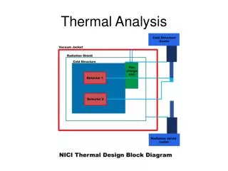
TRACE/FRED model of the ALFRED core • 171 parallel 1D channels and 171 heat structures representing one fuel rod per SA • 3 channels for bypasses -- between FAs; -- through reflector; and -- through CAs • BC on inlet coolant temperature (400C) and flowrate (25458 kg/s)
Power distribution in fuel assemblies and non-fuel regions, MW
Power distribution (D7) • SA-wise power distribution over core radius (CEA)
Power distribution (D7, Figs. 7-11) • SA-wise power distribution and proposal for cooling groups (CEA) CG1 CG2 CG3 CG4
Cooling groups • Proposal for cooling groupsCG1 : 1 – 87CG2 : 88 – 111CG3 : 113 –117 120 – 125 127 – 132 134 – 139 141 – 146 148 – 153CG4 : 112, 119, 126, 133, 140, 147 154 – 171CG 5: 172CG 6: 173CG7: 174
Outlet coolant temperatures • TRACE results : 474 – 491 C. The maximum difference is ~17 C
T62: LFR core thermal hydraulics What is expected? 1D TH analysis of the core?