Download
1 / 40
400 likes | 423 Views
Learn about basic adders like half and full adders, parallel binary adders, comparators, decoders, encoders, code converters, and multiplexers in digital circuits. Explore their designs and applications.

E N D
Chapter 6 Functions of combinational logic
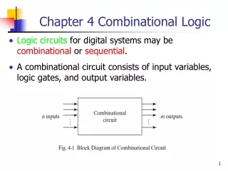
6-1 Basic adders • The half adder The half adder accepts two binary digits on its inputs and produces two binary digits on its outputs, a sum bit and a carry bit. 0+0=0 0+1=1 1+0=1 1+1=10 The operations are performed by a logic circuit called a half-adder.
A Sum Input bits Outputs B Carry Cout Logic symbol for a half-adder
2 The full-adder The full-adder accepts two input bits and an input carry and generates a sum output and an output carry.
A Sum Input bits Outputs B Carry Cout Input carry Cin Logic symbol for a full-adder
6-2 Parallel binary adders Two or more full-adders are connected to form parallel binary adders.
6-4 Comparators The basic function of a comparator is to compare the magnitudes of two binary quantities to determine the relationship of those quantities. In its simplest form, a comparator circuit determines whether two numbers are equal.
Function table input output 1 A 1 0 0 B 1 1 0 0 A>B A=B A<B 0 1 0 0 0 1 1 0 0 0 1 0
1 0 0 1 1 0 1 0 0 0 1 1 1. Equality The exclusive-OR gate can be used as a basic comparator.
COMP A0 A1 A2 A3 0 1 2 3 A>B A A=B B0 B1 B2 B3 0 1 2 3 A<B B 2. Inequality
6-5 Decoders A decoder is a digital circuit that detects the presence of a specified combination of bits (code) on its inputs and indicates the presence of that code by a specified output level. In its general form, a decoder has n input lines to handle n bits and from one to 2n output lines to indicate the presence of one or more n-bit combinations.
Input Output A2 A1 A0 Y7 Y6 Y5 Y4 Y3 Y2 Y1 Y0 0 0 0 0 0 0 0 0 0 0 1 0 0 1 0 0 0 0 0 0 1 0 0 1 0 0 0 0 0 0 1 0 0 0 1 1 0 0 0 0 1 0 0 0 1 0 0 0 0 0 1 0 0 0 0 1 0 1 0 0 1 0 0 0 0 0 1 1 0 0 1 0 0 0 0 0 0 1 1 1 1 0 0 0 0 0 0 0 Truth table
Input Output A2 A1 A0 Y7 Y6 Y5 Y4 Y3 Y2 Y1 Y0 S1 S2+S3 0 X X X X 1 1 1 1 1 1 1 1 1 X 1 X X X 1 1 1 1 1 1 1 1 1 0 0 0 0 0 0 0 0 0 0 1 1 0 0 0 1 0 0 0 0 0 0 1 0 1 0 0 1 0 0 0 0 0 0 1 0 0 1 0 0 1 1 0 0 0 0 1 0 0 0 1 0 1 0 0 0 0 0 1 0 0 0 0 1 0 1 0 1 0 0 1 0 0 0 0 0 1 0 1 1 0 0 1 0 0 0 0 0 0 1 0 1 1 1 1 0 0 0 0 0 0 0 1 0
Example: Use 74HC138 to design a multi-output logic circuit. Z1=AC+ABC+ABC Z2=BC+ABC Z3=AB+ABC Z4=ABC+BC+ABC
The BCD-to-Decimal decoder It is referred as a 4-line-to-10-line decoder.
Common cathode Semiconductor digital tube (a)Outline drawing(b)Equivalent circuit
7-segment character display (Liquid Crystal Display) Common anode Common cathode
6-6 Encoders An encoder is a combinational logic circuit that essentially performs a “reverse” decoder function. An encoder accepts an active level on one of its inputs and convert it to a coded output.
Input Output I0 I1 I2 I3 I4 I5 I6 I7 Y 2 Y1 Y0 1 0 0 0 0 0 0 0000 0 1 0 0 0 0 0 0001 0 0 1 0 0 0 0 0010 0 0 0 1 0 0 0 0011 0 0 0 0 1 0 0 0100 0 0 0 0 0 1 0 0101 0 0 0 0 0 0 1 0110 0 0 0 0 0 0 0 1111 Truth table
6-7 Code converters 1.BCD-to-Binary conversion The process is as follows: • The value, or weight, of each bit in the BCD number is represented by a binary number. • All of the binary representations of the weights of bits that are 1s in the BCD number are added. • The result of this addition is the binary equivalent of the BCD number. A more concise statement of this operation is: The binary numbers representing the weights of the BCD bits are summed to produce the total binary number.
8 7 Example: A decimal number 87 can be expressed in BCD as: 1000 0111 Tens digit Units digit Weight: 80 40 20 10 8 4 2 1 Bit designation: B3 B2 B1 B0 A3 A2 A1 A0
Example: Convert the BCD numbers (decimal 27) and (decimal 98) to binary.
6-8 Multiplexers (Data selectors) A multiplexer (MUX) is a device that allows digital information from several sources to be routed onto a single line for transmission over that line to a common destination. The basic multiplexer has several data-input lines and a single output line. It also has data-select inputs, which permit digital data on any one of the inputs to be switched to the output line.
S1 MUX Data select S0 Y D0 Data output D1 Data inputs D2 D3 Logic symbol
74HC153 Two 4-input multiplexer ——8-input multiplexer
Example: Z =R´A´G´+R´AG+RA´G+RAG´+RAG
Example: Use 8-input multiplexer to complete Z =A´B´C´+AC+A´BC