Op-Amp Explorations
Op-Amp Explorations. Mike Farrell 3/30/2011. Outline. Goals and Setup Op-Amp Input current Simple Inverting Amp Simple Non-Inverting Amp Combine the two Non-Ideal Analysis. Goals. Prove that the ideal Op-Amp model is valid

Op-Amp Explorations
E N D
Presentation Transcript
Op-Amp Explorations Mike Farrell 3/30/2011
Outline • Goals and Setup • Op-Amp Input current • Simple Inverting Amp • Simple Non-Inverting Amp • Combine the two • Non-Ideal Analysis
Goals • Prove that the ideal Op-Amp model is valid • Prove that the non-ideal model is more accurate but not necessary. • Demonstrate how to hook up Op-Amp circuits
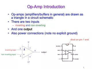
Setup • All Circuits use a LM741C opamp • Power Supply is +- 15V • Ideal Constraints • In=Ip=0 • Vn=Vp • Av=Inf • Rin=Inf • Ro = 0
Input Current Results • Measured Vp and Vn. • I=(0-Vx)/100K (Passive Sign Convention) • All measurements are within spec for data sheet and very close to ideal.
Combo Op-Amp Circuit Combination of Inverting and Non-Inverting Amplifiers
Conclusions • In and Ip <50nA (~0A) • Vn = Vp • Using realistic Av, Rin, and Ro does not have a significant effect on voltage error. • Vout errors all less than 1% from ideal
Slide 14 Questions?