Download
1 / 23
230 likes | 373 Views
Introduction of DAQ system: E906 as an example. Su-Yin Wang (Grass) 2011/06/20. Data Acquisition System. trigger. Front End Electronic. Decoder. Physics Event. Detector. Light Antiquark Flavor Asymmetry: Brief History. Naïve Assumption:. NMC (Gottfried Sum Rule).

E N D
Introduction of DAQ system:E906 as an example Su-Yin Wang (Grass) 2011/06/20
Data Acquisition System trigger Front End Electronic Decoder Physics Event Detector
Light Antiquark Flavor Asymmetry: Brief History • Naïve Assumption: • NMC (Gottfried Sum Rule) • NA51 (Drell-Yan, 1994) • E866/NuSea (Drell-Yan, 1998)
Why Drell-Yan? • To lowest order: • Experimental measurements (E866, CERN NA51 and E906):
Extracting d-bar/-ubar From Drell-Yan Scattering • E906 in NM4 will extend the DY measurements done in E866 120 GeV proton beam (MI) vs 800 GeV proton beam (E866) • E906 expects systematic uncertainty to remain at approx. 1% in cross section ratio.
4.9m E906 Spectrometer E906 Spectrometer Station 2 and 3: Hodoscope array Drift Chamber tracking Hadron Absorber Station 1: Hodoscope array MWPC tracking Solid Iron Focusing Magnet, Hadron absorber and beam dump Mom. Meas. (KTeV Magnet) Station 4: Hodoscope array Prop tube tracking 25m Liquid H2, d2, and solid targets
NM4/KTeV Hall (after installation) HODO 1 HODO 2 Station 3:Drift Chamber HODO 3 Station 4:Proportional Tubes HODO 4
Readout Electronics HODO signal Amplifier High voltage Latch cards Discriminator
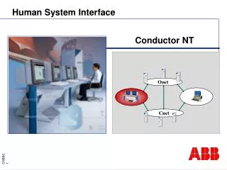
Overview ROC TRIG (~600 ns delay) Latch CPU Hodo TI ROC CODA TS Beam start Beam stop ROC CPU TI TDC St1, St2, St3, St4 Slow Control MySQL Data Control by CODA Trigger We are able to read all Hodo and slowcontrol events now
Adjustable Delay • 64 clocks * 8 ns = 512 ns • Delay=0, earliest signal (default) • Delay=3f, edge signal • Setup: • CSR2(13-8) =11 • CSR2(5-0) =bin (001110) Trigger 8*(63-11)=8*52=416 ns
Latch Card Data Decoding • 0x18ffff32 0xfe000045
Tracking Example • It’s NOT from the Hodos…
But… How to Get Data? • There are two actions though VME bus • Read and Write • Address is the key • All communications are controlled by CPU Latch Card Interrupting Module CPU VME Crate
Write ‘X’ Offset + 0x00C. Set up the user-defined delay range and combination of OR-windows in CSR2. • Write ‘X’ Offset + 0x028. Trigger enabled. LED Red_L should be on.Write ‘X’ Offset + 0x02C. Trigger disabled. • Write ‘X’ Offset + 0x000. Set proper FIFO status mode. • Read Offset + 0x008. Access information of number of events in FIFO. • Read Offset + 0x100. Read Data. Data access 或 Block transfer (BLT).
Now, How Do We Know There is a Tigger Coming? • An interrupting module asserts one of the interrupt request lines. • The interrupter responds by transferring a status/ID on the data bus to describe the interrupt. • The interrupt handling module (usually a CPU) will usually use this status/ID number to identify and run the appropriate software interrupt service routine. Latch Card Interrupting Module CPU VME Crate
Detector (Hodoscopes, MWPC, Prop-tube) CONTROL particle data computer 3 VME crate CPU Trigger system computer 2 Recorder system Offline analyzer Latch TDC Latch TDC Online analyzer Latch TDC Slow Control PAW or ROOT Buffer computer 1 ROOT CODA Collector Offline Analyzer Online Analyzer deCODA Hard disk TCP/IP TPC/IP MySQL
The bus is controlled by a set of nine lines, known as the arbitration bus. All communications are controlled by the card in slot one of the Eurocard chassis, known as the arbiter module. Two arbitration modes are supported - Round Robin and Prioritized. • Regardless of the arbitration mode, a card can attempt to become the bus master by holding one of the four Bus Request lines low. With round robin arbitration, the arbiter cycles amongst Bus Request lines BR0-BR3 to determine which of the potentially-simultaneous requesters will be granted the bus. With priority arbitration, BR0-BR3 use a fixed priority scheme (BR0 lowest, up to BR3 highest) and the arbiter will grant the bus to the highest priority requestor. • When the arbiter has determined which of the bus requests to grant, it asserts the corresponding Bus Grant line (BG0 - BG3) for the level that won bus mastership. If two masters simultaneously request the bus using the same BR line, a bus grant daisy-chain effectively breaks the tie by granting the bus to the module closest to the arbiter. The master granted the bus will then indicate that the bus is in use by asserting Bus Busy (BBSY*). • At this point, the master has gained access to the bus. To write data, the card drives an address, an address modifier and data onto the bus. It then drives the address strobe line and the two data strobe lines low, to indicate the data is ready, and drives the write pin to indicate the transfer direction. There are two data strobes and an *LWORD line, so the cards can indicate if the data width is 8, 16, or 32 bits (or 64 in VME64). The card at the bus address reads the data and pulls the data transfer acknowledge low line when the transfer can complete. If the transfer cannot complete, it can pull the bus error line low. Reading data is essentially the same but the controlling card drives the address bus, leaves the data bus tri-stated and drives the read pin. The slave card drives read data onto the data bus and drives the data strobe pins low when the data is ready. The signalling scheme is asynchronous, meaning that the transfer is not tied to the timing of a bus clock pin (unlike synchronous buses such as PCI).