Download
1 / 16
160 likes | 377 Views
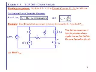
Lecture #13 EGR 260 – Circuit Analysis. Reading Assignment: Sections 4.9 - 4.16 in Electric Circuits, 9 th Ed. by Nilsson . Maximum Power Transfer Theorem Recall that . and . Example : Find R such that maximum power is delivered to R. Also find P max .

E N D
Lecture #13 EGR 260 – Circuit Analysis Reading Assignment:Sections 4.9 - 4.16 in Electric Circuits, 9th Ed. by Nilsson Maximum Power Transfer Theorem Recall that and Example: Find R such that maximum power is delivered to R. Also find Pmax. Note thatmaximum power transfer problems always require that we first find the Thevenin Equivalent Circuit. A) Find VOC:
Lecture #13 EGR 260 – Circuit Analysis Example: (continued) B) Find ISC: C) Find RTH = VOC/ ISC: D) For what value of R is maximum power delivered to R? E) What is Pmax?
Lecture #13 EGR 260 – Circuit Analysis Reading Assignment:Sections 4.9 - 4.16 in Electric Circuits, 7th Ed. by Nilsson Applications of the Maximum Power Transfer Theorem The maximum power transfer theorem is commonly used by engineers. Sometimes the requirement that RL = RTH is referred to as “impedance matching.” Max Power Transfer Theorem application - HF transmitter and antenna
Lecture #13 EGR 260 – Circuit Analysis Max Power Transfer Theorem application - stereo amplifier and speaker
Lecture #13 EGR 260 – Circuit Analysis • PSPICE Demonstration: • Reference: • PSPICE Assignment #2 • Read Chapters 1 - 3 in Schematic Capture Using Cadence PSPICE by Herniter • Handout: PSPICE Example - Maximum Power Transfer (Varying a Component Value) • Handout: PSPICE Example - Op Amp Circuit using a Library Model ( uA741) • Handout: PSPICE Example - Op Amp Example using a General Op Amp Model • DC Sweep: Illustrate how to vary the following quantities: • A voltage source • A current source • A resistor • Insert the part PARAM when varying a resistor value. • Use a potentiometer symbol (part R_VAR) for the resistor • Be sure to change the property SET from 0.5 to 1 • PROBE: Illustrate how to: • Add traces • Add text, arrows, boxes • Add one or two cursors • Mark points on a graph • Find maxima and minima
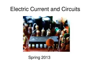
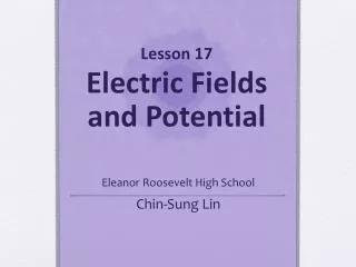
Lecture #13 EGR 260 – Circuit Analysis Reading Assignment:Chapter 6 in Electric Circuits, 7th Ed. by Nilsson Demonstration:Pass around various types of capacitors in class. • Chapter 6 – Capacitors and Inductors • Two new passive components are introduced in this chapter. They are both considered to be energy-storage devices: • Capacitor – stores energy in an electric field • Inductor – stores energy in a magnetic field
Electrons are attracted to the positive terminal of the source leaving a depletion of electrons and a positively charged plate. Charge = +Q - - - + + + + + + + + + + + + + + + + + + + + + + + Total Charge = (+Q) + (-Q) = 0 _ _ _ _ _ _ _ _ _ _ _ _ _ _ _ _ _ _ _ _ _ _ Electrons are repelled by the negative terminal of the source leaving an abundance of electrons and a negatively charged plate. Charge = -Q - - - Lecture #13 EGR 260 – Circuit Analysis Capacitors The simplest type of capacitor is a parallel plate capacitor. Consider the result of placing a voltage across two parallel plates as shown below.
Electric flux lines + + + + + + + + + + E - - - - - - - - - - Lecture #13 EGR 260 – Circuit Analysis Electric field As discussed in Chapter 1, a force is exerted between oppositely charged particles (it can be calculated using Coulomb’s Law). When charged is distributed over a surface (such as with the plates of a capacitor), this force is represented by an electric field, E. The electric field is measured as force per unit charge, or E = F/Q. The electric field is represented by electric flux lines. Recall that a capacitor is an energy storage device – it stores energy in an electric field. Electric fields are studied in depth in a course in electromagnetism. An electric field, E, exists between the charged plates of a capacitor Charge and capacitance The charge on each plate is proportional to the voltage across the plates, so Q V or more specifically Q = CV Typical values:The Farad is a large unit. Most capacitors have capacitance values in the F, nF, or pF range; although some capacitors in the F range are available (generally at low voltages). where C = capacitance
Lecture #13 EGR 260 – Circuit Analysis Capacitor current Recall that current for any device can be found using the relationship: so capacitor current is found as follows: Key relationship:This is sort of like Ohm’s Law for a capacitor. Capacitance symbol The capacitor is a passive device so the relationship above depends on the use of passive sign convention. The general symbol for a capacitor is shown below. Note that the symbol looks like two parallel plates.
Lecture #13 EGR 260 – Circuit Analysis Physical Characteristics Capacitance can also be determined from the physical dimensions of the capacitor using A = Area of plate (in m2) d = distance between plates (in m) where , A, and d are illustrated in the figures shown. Dielectric = material between the plates and = permittivity of the dielectric (in F/m) d
Lecture #13 EGR 260 – Circuit Analysis The permittivity of a given material is often expressed in terms of how it relates to the permittivity of a vacuum using: = Ro where o = permittivity of a vacuum = 8.85 x 10⁻¹² F/m R = relative permittivity (a few examples are shown below) Note: 1 mil = 0.001” Dielectric strength is a measure of how much voltage would be required to jump across a gap, similar to how a spark jumps across the gap on a spark plug. Note that if a spark plug uses a gap of 0.032”, a voltage of = (32 mil)(75V/mil) = 2400V is necessary to create a spark. A dielectric for a capacitor is chosen to insure that the voltage will not arc across the capacitor. So the voltage rating for a capacitor is related to the dielectric strength and the gap size (which affects the value of C).
Lecture #13 EGR 260 – Circuit Analysis Example: Calculate the value of C for a teflon capacitor with rectangular plates that measure 2 cm by 4 cm, and a distance of 0.1 mm between the plates. Also calculate the maximum voltage rating for the capacitor.
Lecture #13 EGR 260 – Circuit Analysis Variable Capacitors Recall that so how can C be varied? 1) by varying d, the distance between the plates 2) by varying A, the area between the plates (actually by rotating one plate to change the amount of overlap between plates). Method 2: Varying A Turning the screw changes the amount of overlap between the plates. Note: Using multiple plates acts like capacitors in parallel which add together (to be proven shortly) Method 1: Varying d Tightening the screw reduces the distance between the plates and increases C. Reference: Intro. Circuit Analysis, 6th Ed., by Boylestad Top view 50% overlap No overlap 100% overlap Reference: All Electonics (www.allelectronics.com Bottom view
Lecture #13 EGR 260 – Circuit Analysis Two categories of capacitors Capacitors are sometimes separated into two categories: 1) Polarized (electrolytic) 2) Non-polarized (non-electrolytic) • Electrolytic capacitors • have polarity markings and may be damaged (or even explode) if used with reverse polarity • often are cylindrical shaped (appear like a metal can) • Electrolytic capacitors are constructed using a large roll of aluminum foil coated with Al·O2 where the aluminum acts as the positive plate and the oxide as the dielectric. A layer of paper is placed over oxide coating and then another roll of aluminum foil without the oxide coating is added to act as the negative plate. This results in a very large plate area, A, and a very small distance, d, between the plates (the thickness of the oxide coating). • most large capacitors (F range) are electrolytic Non-electrolytic capacitors Most small capacitors (nF and pF range) are non-electrolytic
Lecture #13 EGR 260 – Circuit Analysis Capacitor symbols - A special symbol is often used with electrolytic capacitors to designate the negative terminal as shown below. Electrolytic capacitors - images showing internal construction Reference: Oak Ridge National Labs (www.ornl.com) Image 1: External view of an electrolytic capacitor Image 3: Tomographic image of the capacitor showing the roll of foil inside.ctrolytic capacitor showing the roll of aluminum foil (reference: Oak Ridge National Labs (www.ornl.com) Image 2: Digital radiograph of the capacitor showing the roll of foil inside.
Mylar Capacitor (0.22F, 100V) Axial Electrolytic Capacitor (47F, 25V) Metalized Polyester Capacitor (2F, 200V) Ceramic Disc Capacitor (0.22F, 1000V) Monolithic Ceramic Capacitor (22nF) Radial Electrolytic Capacitor (47F, 25V) Snap In Capacitor (330F, 400V) Photo Flash Capacitor (150F, 300V) Super Capacitor (1F, 2.5V) DIP Capacitor (2.2nF, 50V) Lecture #13 EGR 260 – Circuit Analysis Various types of capacitors (reference: All Electronics (www.allelectronics.com)