Download
1 / 38
420 likes | 635 Views
ANALYSIS OF COMPOSITE HYDROGEN STORAGE CYLINDERS UNDER TRANSIENT THERMAL LOADS. J. Hu , S. Sundararaman and K. Chandrashekhara Department of Mechanical and Aerospace Engineering University of Missouri – Rolla William Chernicoff US Department of Transportation Washington, DC 20509.

E N D
ANALYSIS OF COMPOSITE HYDROGEN STORAGE CYLINDERS UNDER TRANSIENT THERMAL LOADS J. Hu , S. Sundararaman and K. Chandrashekhara Department of Mechanical and Aerospace Engineering University of Missouri – Rolla William Chernicoff US Department of Transportation Washington, DC 20509
Outline • Background • Finite Element Model • Resin Reaction Model • Failure Criterion • Temperature Dependent Material Model • Sub-laminate Model • Results • Conclusion
Glass/Epoxy Carbon/Epoxy Carbon/Epoxy Major loading bearing component Carbon/Epoxy Carbon/Epoxy Aluminum liner Background Filament wound Composite Storage Cylinder Composite Cylinder Wall • The inner liner of the cylinder serves as a hydrogen gas permeation barrier • A filament-wound, carbon/epoxy composite laminate provides the desired pressure load bearing capacity • A glass/epoxy layer provides impact and damage resistance
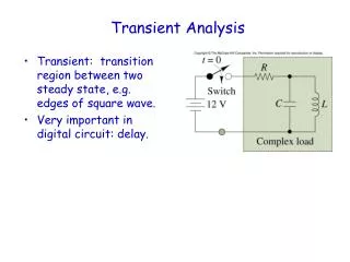
Background (Contd.) Thermal loading • Gas filling process • Environmental temperature change • Exposure to fire Hydrogen storage cylinders Pressure loading (Settled) • 34.5 MPa to 70 MPa Bonfire test
2 1 R2 R1 Finite Element Model The finite element equation for a double curved composite shell where is mass matrix is stiffness matrix is mechanical force loading is thermal force loading Displacement field for a doubly curved shell
Finite Element Model (Contd.) The heat conduction equation can be expressed as where are thermal conductivity, specific heat and density respectively and and are surface heat flux and heat due to resin reaction and flow. Finite element model for transient thermo-mechanical analysis can be written as
Pressure Initialization Mechanical loading Heat flux Compute material modulus, density, and thermal conductivity Resin reaction model Temperature Thermal loading Reaction heat Compute stress and temperature Density Material strength Temperature Stress Strength Failure theory Failure type Failure type Implementation Scheme
Resin Reaction Model Reaction kinetic equation (Arrhenius’s law) is: where - Density - Temperature - Time - Pre-exponential factor - Activation energy - Gas constant
Resin Reaction Model (Contd.) Gas mass flux at any spatial location where - Distance from hot face - Wall thickness of composite Heat of resin decomposition and gas mass flux can be written as where - Specific heat of gas - Specific heat of composite - Heat of decomposition - Ambient temperature
Resin Reaction Model (Contd.) Parameters of resin reaction model used in present study
Failure Criterion Hashin’s criterion (for progressive failure model) Matrix tensile or shear cracking Matrix compressive or shear cracking where are longitudinal tensile strength, longitudinal compressive strength, transverse tensile strength, transverse compressive strength and shear strength of unidirectional ply respectively. For a two-dimensional analysis with transverse shear deformation, is taken as zero.
Failure criterion (Contd.) Fiber tensile failure Fiber compressive failure
Failure criterion (Contd.) Material degradation parameters considered are (S. C. Tan, 1991): Matrix tensile or shear cracking: and where Matrix compressive or shear cracking: and where Fiber tensile failure: where Fiber compressive failure: where
Temperature Dependent Material Model Mechanical and thermal properties of fiber reinforced composites vary significantly with temperature. Hyperbolic tan (tanh) function (A. G. Gibson et. al., 2006) is used to fit the test data for temperature dependent material model. where, P(T) - temperature dependent material property PU - the unrelaxed (low temperature) value of that property PR - the relaxed (high temperature) value of that property k - constant describing the breath of the distribution T - temperature Tg - mechanically determined glass transition temperature C - constant
Temperature Dependent Material Model (Contd.) Curve fitting test data for transverse and shear moduli
Temperature Dependent Material Model (Contd.) The curve fitting parameters for carbon/epoxy are: Longitudinal modulus and strength Transverse modulus and strength Shear modulus and strength
Temperature Dependent Material Model (Contd.) Experimental thermal data for carbon/epoxy (G. Kalogiannakis et. al., 2004 ):
Temperature Dependent Material Model (Contd.) Mechanical properties of S-glass/epoxy As thermal conductivity and specific heat of glass/epoxy are very close to those of carbon/epoxy, the same values are taken for glass/epoxy. Mechanical and thermal properties of Aluminum 6061-T6
Sublaminate Model • Each sublaminate consists of several lamina
Sublaminate Model(Contd.) • Sublaminate homogenization: • In-plane strains and the interlaminar stresses through the thickness are constant. The lamina stress-strain relationship is: (1) where are sub matrices of global stiffness matrix the terms in are constant through the laminate Partially inverting equation (1) and averaging the in-plane stresses and interlaminar strains: (2) where is the thickness of each lamina and is the total thickness of the sublaminate
Sublaminate Model (Contd.) Partially inverting Eq. (2) , yields (3) Equivalent stiffness of the homogenized sublaminate is (4) Equivalent engineering properties can be retrieved by inverting Eq. (4)
Results Hot face Cold face To evaluate the heat transfer model with resin reaction, a simple case is compared with the results available in literature. Cold face temperature variation with time is plotted and compared for a composite panel heated at hot face
Results (Contd.) Modeling • 1/8 of cylinder (diameter 0.44 m) is modeled in ABAQUS • A fine mesh is used at the heat source (diameter0.06 m ) • Symmetric boundary conditions are applied Thermal Load • 75,000 Watt/m2 flux acts on the center circle to simulate the localized fire attack Mechanical Load • Internal pressure is applied on the cylinder Boundary conditions Model mesh
Outer surface S8RT doubly curved shell element Inner surface Results (Contd.) • Sublaminate technique is used to model the composite cylinder wall • The model is implemented in ABQUS FEA code by user subroutine Dimensions Thickness of aluminum liner: 2.54 mm Thickness of each hoop sublaminate: 5.8 mm Thickness of each helical sublaminate: 3.6 mm Thickness of protection layer (S-glass/epoxy) : 4 mm
Inner surface of sublaminate 1 Outer surface of sublaminate 4 Outer surface of sublaminate 5 Outer surface of sublaminate 6 Outer surface of S-glass/epoxy sublaminate Temperature Distribution Temperature of various locations in thickness direction at the heat source
Temperature Distribution path Temperature distribution along the path
S-glass/epoxy Sublaminate Sublaminate 6 Sublaminate 5 Sublaminate 4 Sublaminate 1 Residual Resin Content Residual resin content varies with time at different locations in thickness direction at the heat source
path Density change along path Residual Resin Content
path Stress Distribution in Liner Stress distribution in liner (1000 second ) Stress distribution along path
Stress Distribution in Sublaminate 6 (Hoop layer) path Longitudinal stress distribution in sublaminate 6 (1000 sec ) Stress distribution along path Transverse stress distribution in sublaminate 6 (1000 sec ) Shear stress distribution in sublaminate 6 (1000 sec )
path Stress Distribution in Sublaminate 5 (Helical Layer) Longitudinal stress distribution in sublaminate 5 (1000 sec ) Stress distribution along path Shear stress distribution in sublaminate 5 (1000 sec ) Transverse stress distribution in sublaminate 5 (1000 sec )
Composite Cylinder Failure Time = 1 Sec Time = 1000 Sec SL – sublaminate, 0 – no failure, 1 – matrix failure, 2 – fiber break • For a pressure of 34.5 MPa, no failure occurs due to mechanical load. Matrix failure occurs during fire exposure in the layers close to the heat source (sublaminates 5 and 6). • For a pressure of 48 MPa, no failure occurs due to mechanical load. Matrix failure occurs during fire exposure in the all the layers. • For a pressure of 69 MPa, matrix failure occurs due to mechanical load. • For a pressure of 86 MPa, matrix failure occurs due to mechanical load. Fiber break occurs due to localized heat source.
Conclusions • A comprehensive finite element model is developed accounting for temperature dependent material properties, resin reaction and progressive failure model. • Under localized fire exposure, the temperature of outermost layer increases rapidly around the heat source, however, the temperature increase in the cylinder inner layers and adjacent area is not significant. • Under localized fire exposure, resin is depleted quickly in the outermost layers and very slowly in inner layers. The resin depleted area may cause fiber breakage during the cool down process which may be a safety concern. • For lower internal pressures, localized fire exposure cause matrix failure in and around the regions of the heat source. • Under high internal pressures, localized fire exposure initiates fiber breakage and may cause overall failure of the cylinder.
Continuing Efforts • Continued refinement of the model – evaluation of heat transfer to a PRD and other safety devices • Comparison to physical test • NHTSA • Other
Thank you K. Chandrashekhara chandra@umr.edu http://www.umr.edu/~chandra/ William Chernicoff william.chernicoff@dot.gov http://hydrogen.dot.gov