Download
1 / 17
170 likes | 307 Views
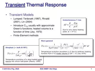
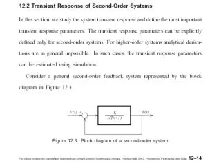
Transient thermal + fatigue analysis in ASONIKA. Specify a name for the project. Select 3d model to import. Quarter-symmetry model of PCB + BGA Package. Specify initial temperature for entire model (20 degrees C).

E N D
Specify initial temperature for entire model (20 degrees C) This temperature will be also used as reference temperature for thermal stress calculation
Select external surfaces and set the thermal condition:convection and radiation (from these surfaces) to the environment Specify film coefficient, emissivity, view factor and ambient temperature values
Surfaces with thermal conditions become meshed Symmetry planes should not have thermal conditions
Select the volume (that represent the silicon chip) and set it as a heat power source
For transient thermal analysis heat power source can be time dependent Input heat power vs time curve. In this example two thermal cycles are modeled. Time dependent heat power will cause cyclic temperatures and stresses. Cyclic thermal stresses are used for fatigue calculation One thermal (heat power) cycle has range of 8-18 Watt (2-4.5 Watt for quarter symmetry model)
Set material properties for all parts of the modelFor solder balls the following parameters will be used:
Set solution parameters Specify the end time of the analysis, the time integration step and the number of thermal cycles contained in the solution interval
Temperature – time curve at nodes Two arbitrary nodes were selected Temperature vs time curves for two nodes
Stress-time curve Two arbitrary nodes were selected Stress vs time curves for two nodes
Fatigue plot Plot shows minimum fatigue life (451.9 thermal cycles) in solder balls