Transient Analysis in Electric Circuits
Learn about transient responses, second-order circuits, and more in this comprehensive guide to transient analysis in electric circuits.

Transient Analysis in Electric Circuits
E N D
Presentation Transcript
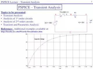
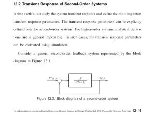
CHAPTER5 Transient Analysis
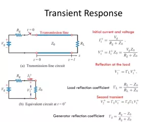
Figure 5.1 Examples of transient response Figure 5.1 5-1
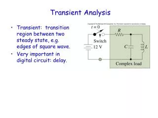
Figure 5.2, 5.3 Circuit with switched DC excitation A general model of the transient analysis problem Figure 5.2 Figure 5.3 5-2
Figure 5.5, 5.6 Circuit containing energy storage element Figure 5.5 Figure 5.6 5-3
Figure 5.7, 5.8 Second-order circuit Second-order circuit of Example 5.2 Figure 5.7 Figure 5.8 5-4
Figure 5.9, 5.10 (a) Circuit for Example 5.3; (b) same circuit a long time after the switch is closed Figure 5.9 (a) Circuit for Example 5.4; (b) same circuit a long time before the switch is opened Figure 5.10 5-5
Figure 5.12, 5.13 Figure 5.12 Figure 5.13 5-6
Figure 5.15 First-order exponential decay and time constants Figure 5.15 5-7
Figure 5.17, 5.18 Figure 5.17 Figure 5.18 (a) Complete, transient, and steady-state responses of the circuit of Figure 5.17; (b) complete, natural, and forced responses of the circuit of Figure 5.17 5-8
Figure 5.30, 5.31, 5.32 Figure 5.30 Figure 5.32 Figure 5.31 5-9
Figure 5.38 Second-order circuits Figure 5.38 5-10
Figure 5.42 Response of switched second-order system with Ks = 1, ωn = 1, and ζ ranging from 0.2 to 4 Figure 5.42 5-11
Figure 5.45 Natural response of underdamped second-order system for α1 = α2 = 1; ζ = 1.5; ω n = 1 Figure 5.45 5-12
Figure 5.46 Natural response of a critically damped second-order system for α1 = α2 = 1; ζ = 1; ω n = 1 Figure 5.46 5-13
Figure 5.47 Natural response of an underdamped second-order system for α1 = α2 = 1; ζ = 0.2; ω n = 1 Figure 5.47 5-14
Figure 5.56 Figure 5.56 5-15
Figure 5.57 (a) First-order transient circuit (b) Second-order transient circuit, following opening of switch Figure 5.57a Figure 5.57b 5-16
Figure 5.58 Transient current response of ignition current Figure 5.58 5-17
Figure 5.59 Secondary ignition voltage response Figure 5.59 5-18