Download

1 / 9
90 likes | 240 Views
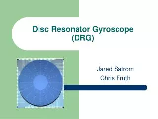
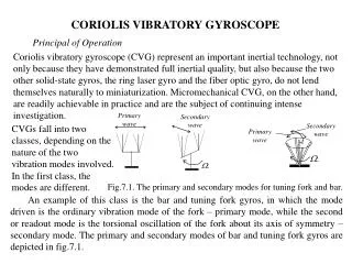
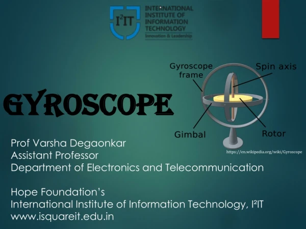
Modeling of a Gyroscope. Background and Motivation. Device to measure or maintain orientation Modeling a mechanical type of gyroscope Based on the principles of angular momentum. Geometry and Connections. All components are assumed rigid.

E N D
Background and Motivation • Device to measure or maintain orientation • Modeling a mechanical type of gyroscope • Based on the principles of angular momentum
Geometry and Connections All components are assumed rigid Hinge Joints are used to connect different parts Outer Gimbal Spinning Disc Frame Inner Gimbal
Material • Structural Steel (ρ = 7850 kg/m^3): Spinning Disc • Aluminum (ρ = 2700 kg/m^3): All other components NOTE: Structural Steel is chosen for the Spinning Disc to increase its angular momentum at comparatively low rotational speed.
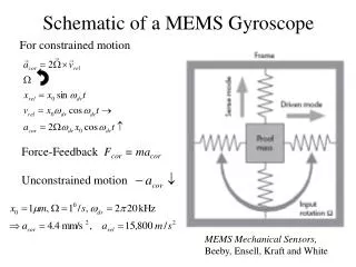
Operating Conditions • Motion of outer Frame is prescribed in such a way that, at the center of mass: • No translation • Rotation: 2*sin(π*t) radabout (1,1,0) axis • The Spinning Disc is rotating with respect to the Inner Gimbal: • Angular velocity: 100 rad/sec
Model Setup • All components are assumed rigid, which makes it possible to model only one Hinge Joint between any two components instead of two. • The joint axes passes though the origin (0,0,0) for all the Hinge Joints such that the center of the joints can be kept at the origin for all joints. • This model is solved for 1 secand the results are stored at the interval of 1e-2 sec. • However, the maximum allowed time step is 5e-4 sec. This is needed as the Spinning Disc is rotating at very high speeds and completes almost 16 revolutions (100 rads)in 1 sec.
Results Animation of gyroscope when disc is not spinning
Results Animation of gyroscope when disc is spinning at 100 rad/s
Conclusions • The results show that the Spinning Disc,when it is not spinning,experiences unbalanced forces and moments due to the motion prescribed to the outer Frame. • This is the reason why the Spinning Disc changes its orientation and does not remain vertical. • In the case when the Spinning Disc is rotating at high speeds, there is a large amount of angular momentum associated with this. • This angular momentum resists the unbalanced forces and moments and helps the disc to maintain its orientation close to the vertical.