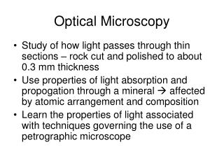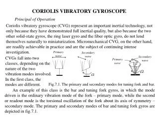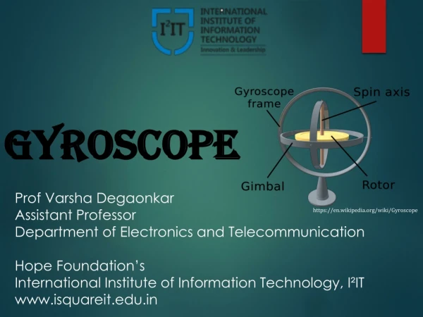
Optical Gyroscope
Optical Gyroscope. Arman Cingoz 11/3/04. Outline. Sagnac Effect Passive Ring Resonator Gyro (Fiber Gyro) Active Ring Resonator (Laser Gyro) Applications Future. Sagnac Effect. First experiments concerning light propagation in rotating media were carried out by F. Harress in 1911.

Optical Gyroscope
E N D
Presentation Transcript
Optical Gyroscope Arman Cingoz 11/3/04
Outline • Sagnac Effect • Passive Ring Resonator Gyro (Fiber Gyro) • Active Ring Resonator (Laser Gyro) • Applications • Future
Sagnac Effect • First experiments concerning light propagation in rotating media were carried out by F. Harress in 1911. • George Sagnac published his results in 1913 and is credited with the effect since Harress made numerous errors in interpretation of his experiment • A thought experiment:
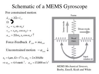
Sagnac Effect continued • A more realistic situation is an N sided regular polygon:
Sagnac effect continued • Let us put in some numbers: d=10 cm, A = 45 cm2, l= 633 nm, W = 15 deg/hr =7.3*10-5 rad/s Df = 4.2*10-8 rad • B. Pogany experimented with an 80 kg device trying to rotate at 1600 rpm. He reported that all optical parts were damaged due to vibration by 600 rpm. • Michelson used 5 miles of evacuated sewer pipes to measure the rotation of the Earth.
Fiber Gyro • To increase effective area, we can wind N loops of fiber optic cable. • The output intensity is modulated by the phase shift between the two beams.
Fiber Gyro Continued • The dynamic range of the device is easily configurable using the length and the diameter of the fiber loop. • For example, l = 850 nm, L = 1 km, D = 10 cm ÞWp= 73 deg/s For 1m rad sensitivity Þ Wm = 0.084 deg/h • For example, l = 850 nm, L = 100 m, D = 3 cm ÞWp= 2400 deg/s For 1m rad sensitivity Þ Wm = 2.8 deg/h
Sources of Noise • Fundamental Limitations · Sensitivity is limited by shot noise that goes as the square root of the power. · The power received at the detector decreases with fiber length: · However, the Sagnac effect increases with the length of the fiber. These two competing effects set the length of the fiber for a given sensitivity. · For a sensitivity of 10-3 deg/h, L is roughly few kilometers.
Sources of Noise • Thermal Noise ·Time dependent temperature gradient along the length of the fiber can introduce spurious phase shifts due to the temperature dependence of the index of refraction and the cable. · For dt = 1 h, D = 20 cm, L = 1.56 km, dn/dT = 10-5 /0C, a = 5*10-7 /0C, n=1.45, and calculated shot noise limit of 0.0078 deg/h, DT needs to be 6.7*10-3 /0C. · Use fibers with smaller dn/dT · Wind the coil such that equidistant points from fiber center are physically close to each other.
Sources of Noise • Polarization and Birefringence · Single mode fibers permit transmission of two orthogonal polarizations · Mechanical stresses can cause power transfer between polarizations and birefringence which changes the wave velocity. The result is a superposition of two interference patterns that lead to poor contrast and fringe shifts. · Polarizers were initially used to suppress the weak polarization · Polarization preserving fibers with high birefringence is used to suppress the weak polarization.
Sources of Noise • Backscatter and Beam to Filter Coupling · Backscatter at the output-input couplers can interfere with the main beams creating parasitic interferometers. · A reasonable criterion is that the reflected power should be on the order of the intrinsic Rayleigh scattering. Since in a 1 m long, single mode fiber, the approximate value for the backscattered power is –60 dB, the reflected power at the input/output interface should be less than 10-6 times the beam power. · Antireflective coating on fiber surfaces is not enough as a solution. · Immersion cell to reduce index of refraction step. · Production of fibers with slanted end faces
Sources of Noise • Optical Kerr Effect · Electric fields of the counter-propagating beams can cause changes in the index of refraction that is nonreciprocal if |E1| and |E2| are not equal (I1/I2 = ±10-4 leads to 10-3 deg/h shifts, Bergh et. al.1982). · A clever way to eliminate this problem is a square wave modulation
Laser Gyro • Introduce an active laser medium into the cavity. This effectively converts phase changes to frequency changes. • The intensity is modulated at the beat frequency: • d=10 cm, A = 45 cm2, l= 633 nm, W = 15 deg/hr =7.3*10-5 rad/s Dn = 7 Hz
Sources of Errors • Null Shift · The beat frequency is nonzero even when W=0 · Langmuir flow: In active laser media, neutral atoms along the center of the discharge move toward the cathode while the atoms near the walls move toward the anode. Since the lasing light is concentrated in the center, the two counter propagating beams see opposite motion for the lasing medium and hence different index of refraction (Fressnel drag). · Use two discharge tubes
Sources of Errors • Mode Locking · Backscattering in the optical path (mirrors) weakly couples the counter propagating beams. If the beat frequency gets smaller than a threshold value, the modes oscillate at the same frequency, eliminating the beat note. where and · For SW<b, there is a stable solution where · WTH» b/S = 400 deg/h for b=103 rad/s
Avoiding Mode Locking • Constant Bias · Add a large constant bias such that within the operating range SW+a>b, where a is the bias. · Problem is that we need to keep a large bias very stable and know its value very precisely to be able to subtract it later on. · Mechanical rotation is not stable enough · Faraday effect: Applying a magnetic field parallel to the direction of propagation leads to polarization rotation by angle b=VBd. However, the rotation is the same for in either direction leading to a frequency shift:
Avoiding Mode Locking • Alternating Bias · Alternate bias in positive and negative directions. Over each cycle the net bias averages out eliminating the need to know the amplitude very precisely. a,w>>b · The solution of this differential equation shows that there are “dead bands” centered at the multiples of the dither frequency with width:
Avoiding Mode Locking · Dead spaces can be made very small since by choosing a/w large
Canterbury Laser Gyro • Currently CII is world’s largest laser gyro with approximate area of 1m2 • Made out of one solid piece of Zerodur using HeNe as the active lasing medium • Sensitivity of 10-7 Earth rotations over many hours: 10-8 rad/s/Hz-1/2 • Can detect 12 mHz oscillations in the earth’s rotation axis due to the moon (60 cm daily motion at the poles) • Currently designing a 367 m2 gyro with estimated sensitivity of 10-10 rad/s/Hz-1/2
Applications • Navigation • Geophysics • Relativity • Symmetry testing • Quantum Field Theory
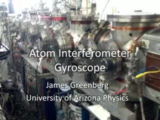
Atomic Gyro • For matter waves, the phase shift equation is modified as, • !!! • Gustavson et. al. 1996: A = 22 mm2, sensitivity of 2*10-8 rad/s/Hz-1/2 • Space based: HYPER (European Space Agency) Space Matter Wave Gyroscope (Jet Propulsion Laboratory)
References • Chow W., et. al., The ring laser gyro, Rev. Mod. Phys, 1985, 57, 61 • Lefevre, H., The Fiber-Optic Gyroscope, (Artech House) 1993 • Gustavson, T, et. al., Precision Rotation Measurements with an Atom Interferometer Gyroscope, Phys. Rev. Lett., 1996, 71, 2046 • Bergh, R. , et. al., Compensation of the optical Kerr effect in fiber-optic gyroscopes, Opt. Lett., 1982, 7, 6 • Stedman, G., Ring-laser tests of fundamental physics and geophysics, 1997, Rep. Prog. Phys., 60, 615 • Loukianov, D., et. al. (ed.), Optical Gyros and their Application, RTO AGARDoraph 339, 1999