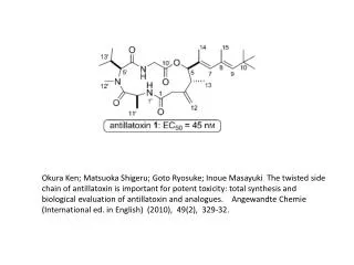
cdma2000 Reverse Link
520 likes | 850 Views
cdma2000 Reverse Link. Section Introduction. Reverse Link Channels Pilot Channel Enhanced Access Channel Common Control Channel Fundamental and Supplemental Channels Reverse Radio Configurations Reverse Link Characteristics Inter-frequency Hard Handoffs RL Power Control.

cdma2000 Reverse Link
E N D
Presentation Transcript
Section Introduction • Reverse Link Channels • Pilot Channel • Enhanced Access Channel • Common Control Channel • Fundamental and Supplemental Channels • Reverse Radio Configurations • Reverse Link Characteristics • Inter-frequency Hard Handoffs • RL Power Control
cdma2000 Reverse Channels R-ACH* Reverse Access Channel R-CPHCH Reverse Common Physical Channel R-EACH Reverse Enhanced Access Channel R-CCCH Reverse Common Control Channel * Backward Compatible Channel
RL Radio Configurations * Maximum data rate for a single Supplemental Channel ** Radio Configuration 1 and 2 correspond to TIA/EIA-95-B RS 1 and RS 2
Reverse Link Characteristics • Channels are primarily code multiplexed • Separate channels used for different QoS and physical layer characteristics • Transmission is continuous to avoid EMI issues • Code Multiplexed channels are orthogonalized by Walsh functions and I/Q split so that performance is equivalent to BPSK • Hybrid Combination of QPSK and Pi/2 BPSK • By restricting alternate phase changes of the complex scrambling sequence, power peaking is reduced (1 dB improvement) and side lobes are narrowed • Code multiplexed channels • Walsh Sequence separate physical channels • Forward Error Correction • Convolutional codes (K=9) are used for voice and data • Parallel Turbo Codes (K=4) are used for high data rates on Supplemental • Fast Reverse Power Control • 800 Hz update rate • Frame Lengths • 5 ms, 10 ms, 20 ms, 40 ms and 80 ms frames
Reverse Pilot Channel • The Reverse Pilot Channel is transmitted when Enhanced Access Channel, Common Control Channel, or the Reverse Traffic Channel with Radio Configuration 3 through 6 is enabled. • The Reverse Pilot Channel is also transmitted during Enhanced Access Channel preamble, Common Control Channel preamble, or the Reverse Traffic Channel preamble. • Pilot reference level varies across Radio Configurations.
Enhanced Access Channel • The R-EACH is used by the MS to initiate communication with the BS or respond to a MS directed message • The R-EACH can be used in three possible modes: Basic Access Mode, Power Control Access Mode, and Reservation Access Mode. • Basic Access Mode: preamble + data (No header) • Power Control Access Mode: preamble + header + data • Reservation Access Mode: preamble + header (data is sent on the Reverse Common Control Channel) • Frame length • 5 ms frame for header • 5 ms, 10 ms, or 20 ms for data
Reverse Common Control Channel • The R-CCCH is used for the transmission of user and signaling information to the BS when Reverse Traffic Channels are not in use. • Up to 32 R-CCCH per supported F-CCCH and up to 32 R-CCCH per supported F-CACH • Structure similar to Reverse Dedicated Channel • No FL power control puncturing on pilot • Access probes are staggered in time (5 ms) • Reduces delay • Multiple MS can be simultaneously captured by receiver • Frame length: 20 ms, 10 ms, or 5 ms
Reverse Dedicated Control Channel (R-DCCH) • The R-DCCH is used for transmission of user and signaling information to the base station during a call • The R-DCCH frame structure is shown in the following table:
R-DCCH Structure RC 3 RC 4
Reverse Supplemental Channel • Up to 2 Supplemental Channels are possible • Applies only to Radio Configuration 3 to 6 • Turbo coding may be used for Radio Configuration 3 to 6 • Supports 20 ms, 40 ms, and 80 ms frames • Reverse Supplemental Channel physical layer frame structure • There are always 8 reserved/tail bits • CRC length is 16 bits for 360 or more bits/frame • Reserved bit is included if rate is an IS-95 rate
Signal Constellation Before Spreading RC 3 and Above (R-FCH, and R-SCH 1) Q I RC 3 and Above (R-PICH, R-DCCH, R-SCH2)
HPSK/ OCQPSK • Hybrid PSK (HPSK)/Orthogonal Complex QPSK (OCQPSK) • Reduces Peak-to-average ratio • Reduces linearity requirements of the PA
Long Code Generator for SR 3 • The I long code generator for SR 3 consists of three multiplexed components: • The first component is the I long code for SR 1 • The second component is the modulo-2 addition of the I long code and the I long code delayed by 1/1.2288 s • The third component is the modulo-2 addition of the I long code and the I long code delayed by 2/1.2288 s • The chip rate of the long code is 3.6864 Mcps
Reverse Pilot Gating • Used when the mobile station is in control hold to reduce battery consumption
Reverse Pilot Gating during R-DCCHTransmission (5 ms Frame) • Note that during a R-DCCH transmission the power control rate remains the same • Why? The base station does not know that the mobile station is transmitting on the R-DCCH
Reverse Pilot Gating during R-DCCHTransmission (20 ms Frame)
RL Open Loop Power Control • Reverse link power control is based on and referenced to the Pilot Channel • The initial transmission on the Reverse Pilot Channel when transmitting Reverse Traffic Channel with RC 3, 4, 5, or 6 • Where interference correction = min(max(IC_THRESs - ECIO,0),7), and ECIO is the Ec/Io (dB) per carrier of the strongest active set pilot, measured within the previous 500 ms. • RL_GAIN_ADJ is sent in the Extended Channel Assignment Message (ECAM)
RL Power Control • After the first valid power control bit is received, the mean pilot output power is defined by
RC1 and 2 Versus RC3 and Above Power Control • With RC1 and RC1 • The base station estimates the E/N0 using 6 consecutive Walsh functions transmitted by the MS • The E/N0 estimate is then compared to a threshold to determine the sign of the power control bit • With RC3 and above • The base station filters the pilot channel to obtain an E/N0 estimate • The E/N0 estimate is then compared to a threshold to determine the sign of the power control bit • The RC3 type power control • Is a constant 800 bps • Is independent of data rate except when gating modes are used
RL Closed Loop Power Control • The MS adjusts its mean output power based on the valid power control bit received on the F-FCH or F-DCCH • 0.25 dB, 0.5 dB, and 1.0 dB power control step sizes are supported • The MS is required to support a 1.0 dB stepsize • If the MS supports the R-SCH, then it must support a 0.5 dB stepsize • The MS is told the stepsize in the Power Control Message (PCNM)
RL Code Channel Output Power (RC 3, 4, 5, or 6) • Nominal_Attribute_Gain is a table stored in the MS • Attribute_Adjustment_Gain permits the table to be updated via the PCNM (Power Control Message) • Reverse_Channel_Adjustment permits the gain for a particular channel to be updated via the PCNM • Multiple_Channel_Adjustment handles variations due to various pilot setpoints • RLGAIN_TRAFFIC_PILOT is an overhead parameter used to adjust the traffic to pilot ratios • RLGAIN_SCH_PILOT is parameter in certain messages to adjust traffic to pilot ratios
Multiple Channel Adjustment • Goal is to make the Fundamental Channel output power constant
Transmitter Filter 1X Filter 3X Filter
Coupling 1X and 3X Together • It has been proposed to couple 1X reverse link with 3X forward link • MC forward link can be sent through different power amplifiers, which don’t have intermodulation between them • For many applications, higher reverse link data rates are not needed; • Provides much less out-of-band interference