Download
1 / 109
1.09k likes | 1.11k Views
The Ottawa Hills Dam Decommissioning Project. Constructed: August 2008. At the request of the Village of Ottawa Hills we did not work in this bend even though the vertical bank is 7 ft tall and the water over 7 ft deep!!.

E N D
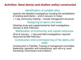
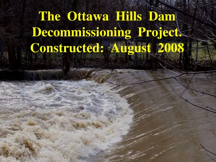
The Ottawa Hills Dam Decommissioning Project. Constructed: August 2008
At the request of the Village of Ottawa Hills we did not work in this bend even though the vertical bank is 7 ft tall and the water over 7 ft deep!! This project will encompass the bends immediately upstream and downstream of the former dam site US Project Limit Existing riffle constructed by ODOT Conceptual Design Illustration of Restoration Site by Matt Horvat of TMACOG DS Project Limit
The Ottawa Hills Dam Decommissioning ProjectThe dam was removed by Ohio-DOT in November 2007.The project described in this PowerPoint is designed to reduce bank erosion and protect public infrastructure (two roads), create aquatic & riparian habitat, improve streamside vegetation, assist with improving the riparian area, provide benches & stepping stones for public stream enjoyment and access, and still have the existing mowed floodplain recreation areas for public use!
Looking from left bank at the Secor Road dam. OTTAWA R-DAM REMOVAL @ OTTAWA HILLS-PIX BY MATT HORVAT-2007
Typical condition US of the Secor Road dam. OTTAWA R-DAM REMOVAL @ OTTAWA HILLS-PIX BY MATT HORVAT-2007
Looking from left bank @ trackhoe removing the dam. OTTAWA RIVER-DAM REMOVAL @ OTTAWA HILLS-PIX-LAWRENCE-2007
Looking US @ trackhoes removing dam OTTAWA RIVER-DAM REMOVAL @ OTTAWA HILLS-PIX-LAWRENCE-2007
Looking US. Dam out, right bank sheetpile out, concrete riffle in. Left bank sheetpile will stay. OTTAWA RIVER-DAM REMOVAL @ OTTAWA HILLS-PIX-HORVAT - 2007
PRE-PROJECT PHOTOS STARTING FROM UPSTREAM TO DOWNSTREAMby Dave Derrick AUGUST 20, 2008
Looking DS. High velocity current is eroding the right bank, then crosses over & erodes the left bank in the crossing. Note how deep Matt is. Matt went in over his head when he ventured near the right bank. At the request of the Village of Ottawa Hills, the right bank was not stabilized. PRE-PROJECT-OTTAWA RIVER @ OTTAWA HILLS. PIX-DERRICK 8-20-2008
Looking DS @ left eroded bank in the crossing & the upper portion of the US project bend. PRE-PROJECT-OTTAWA RIVER @ OTTAWA HILLS. PIX-DERRICK 8-20-2008
Looking US @ the lower end of the US project bend PRE-PROJECT-OTTAWA RIVER @ OTTAWA HILLS. PIX-DERRICK 8-20-2008
At the former dam site, looking US into the US bend PRE-PROJECT-OTTAWA RIVER @ OTTAWA HILLS. PIX-DERRICK 8-20-2008
Looking DS @ the DS project bend. Hill Ditch tributary comes in just US of the bend. PRE-PROJECT-OTTAWA RIVER @ OTTAWA HILLS. PIX-DERRICK 8-20-2008
Looking DS @ the DS project bend & the Secor Road bridge. PRE-PROJECT-OTTAWA RIVER @ OTTAWA HILLS. PIX-DERRICK 8-20-2008
Looking DS. The protection will tie into the existing bridge abutment protection right here. PRE-PROJECT-OTTAWA RIVER @ OTTAWA HILLS. PIX-DERRICK 8-20-2008
At the request of the Village of Ottawa Hills we did not work in this bend even though the vertical bank is 7 ft tall and the water over 7 ft deep!! This project will encompass the bends upstream and downstream of the former dam site US Project Limit Existing riffle constructed by ODOT Conceptual Design Illustration of Restoration Site by Matt Horvat of TMACOG DS Project Limit
The Cat 330 tracked back hoe with a 4 ft wide bucket, 25 ft reach, weight about 70,000 pounds CONSTRUCTION-OTTAWA RIVER @ OTTAWA HILLS. PIX-DERRICK 8-2008
SUITABLE STONEStone used for keys and LPSTP was a well-graded, self-adjusting, self-filtering Class A Stone with a size of 18” to 36” on the “B” axis. Stone for the Bendway Weirs & Traffic Control Stones was a specially produced armor stone that varied from 2’ by 2’ by 3’ to 4’ by 4’ by 5’.
Dumping “A”stone-18 to 36 inch sized stone CONSTRUCTION-OTTAWA RIVER @ OTTAWA HILLS. PIX-DERRICK 8-2008
Staged “A”-stone and armor stone CONSTRUCTION-OTTAWA RIVER @ OTTAWA HILLS. PIX-DERRICK 8-2008
Methodologies for the Upstream Bend • Traffic Control Stones with short Bendway Weirs • Vegetated keys • Transplanted clumps of shrubs • Hydraulic Cover Stones • Planned fall 2008: Container plantings of dogwoods, fast and slow growing shade trees, chokecherry, buttonbush, & other shrubs for food, pollinators, etc.
A KEY HAS ONE MAIN JOB, TO CONNECT THE RIVER TRAINING STRUCTURE TO THE REST OF THE WORLD (DON’T LET THE STREAM GET BEHIND {FLANK} RIVER TRAINING STRUCTURES)
CONSTRUCTION PHOTOSby Dave Derrick & Matt HorvatAugust 20-25, 2008
Detail for key Flow Cross-section for keyway
Looking uphill at the dug key trench Flow CONSTRUCTION-OTTAWA RIVER @ OTTAWA HILLS. PIX-DERRICK 8-2008
Detail for key Flow Place some stone & soil in the trench
Placing some graded “A” stone and soil in the trench Flow CONSTRUCTION-OTTAWA RIVER @ OTTAWA HILLS. PIX-DERRICK 8-2008
Place Willow Poles against DS side of trench. Detail for key Flow
Placing willow poles in the key trench CONSTRUCTION-OTTAWA RIVER @ OTTAWA HILLS. PIX-DERRICK 8-2008
Key will be extended uphill where the hoe is parked Flow CONSTRUCTION-OTTAWA RIVER @ OTTAWA HILLS. PIX-DERRICK 8-2008
Place the remainder of the stone in the trench Detail for key Flow
Placing “A” stone within 1 ft of the surface of the trench CONSTRUCTION-OTTAWA RIVER @ OTTAWA HILLS. PIX-DERRICK 8-2008
Choke stone with soil & water in. Detail for key Flow
Backfill with native soils. CONSTRUCTION-OTTAWA RIVER @ OTTAWA HILLS. PIX-DERRICK 8-2008
Backfill and overfill with native soils, then compact (some settling will still occur) Detail for key Flow
Compacting soil over key. Note poles on DS side of key CONSTRUCTION-OTTAWA RIVER @ OTTAWA HILLS. PIX-DERRICK 8-2008
WHAT IS THE LOWER LIMIT OF HARD BANK PROTECTION?AND MORE IMPORTANT, HOW CAN WE REACH IT?
TRAFFIC CONTROL STONES (TCS) WITH SINGLE-STONE OR SHORT BENDWAY WEIRS
Traffic Control Stones for the US project bend Drawn by Matt Horvat, TMACOG
Key Traffic Control Stones with Single Stone Bendway Weirs TCS TCS TCS Key TCS TCS SSBW TCS TCS TCS SSBW Key TCS SSBW Large stones (3 ft by 3 ft by 3 ft) designed to “kick” flow off the bank, must be keyed into the bed & bank, spaced 6 to 8 ft apart, every 3rd one should be keyed into the bank. Every 3rd stone has a Single Stone or short Bendway Weir.