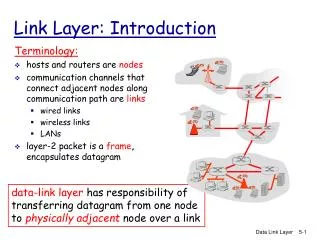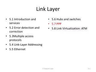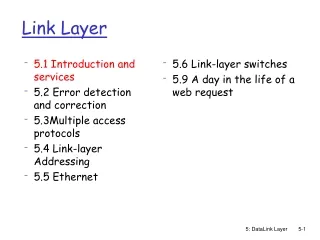
Link Layer Functions
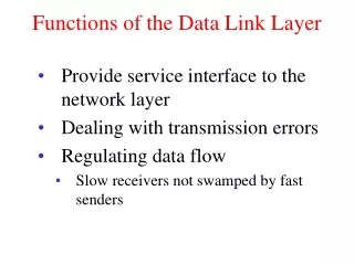
Link Layer Functions. Between two adjacent machines – reliably and efficiently Framing service Interface between network layer (packet) and physical layer (bit) encapsulate data packet into frame, adding header, trailer channel access if shared medium

Link Layer Functions
E N D
Presentation Transcript
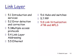
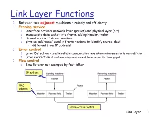
Link Layer Functions • Between two adjacent machines – reliably and efficiently • Framing service • Interface between network layer (packet) and physical layer (bit) • encapsulate data packet into frame, adding header, trailer • channel access if shared medium • ‘physical addresses’ used in frame headers to identify source, dest • different from IP address! • Error control • Error Detection - Used in reliable communication links where retransmission is more efficient • Error Correction - Used in a noisy environment to increase the throughput • Flow control • Slow listener not swamped by fast talker IP address MAC address Media Access Control Link Layer
link layer implemented in “adaptor” (aka NIC) Ethernet card, PCMCIA card, 802.11 card sending side: encapsulates datagram in a frame adds error checking bits, rdt, flow control, etc. receiving side looks for errors, rdt, flow control, etc extracts datagram, passes to rcving node adapter is semi-autonomous frame frame Adaptors Communicating datagram rcving node link layer protocol sending node adapter adapter Link Layer
Framing Methods– identify the frame Count may be garbled => out of sync • Byte-oriented Frame: Character count, Flag byte with byte stuffing (character stuffing) Resync if needed STX, ETX Limitation: binary data, unicode Link Layer
Framing Methods – Bit oriented frame • Bit-oriented Frame: Starting / ending flag, bit stuffing HDLC High level data link control Ethernet Link Layer
All inputs to channel satisfy pattern or condition Channel output Deliver user information or set error alarm Pattern checking User information Encoder Channel Key Idea • All transmitted data blocks (“codewords”) satisfy a pattern • If received block doesn’t satisfy pattern, it is in error • Redundancy: Only a subset of all possible blocks can be codewords • Blindspot: when channel transforms a codeword into another codeword Link Layer
Error Detection EDC= Error Detection and Correction bits (redundancy) D = Data protected by error checking, may include header fields • Error detection not 100% reliable! • protocol may miss some errors, but rarely • larger EDC field yields better detection and correction Link Layer
Received information bits Information bits Recalculate check bits k bits Channel Calculate check bits Received check bits Compare Sent check bits Information accepted if check bits match n – k bits Checkbits & Error Detection Link Layer
Info Bits: b1, b2, b3, …, bk Check Bit: bk+1= b1+ b2+ b3+ …+ bk modulo 2 Codeword: (b1, b2, b3, …, bk,, bk+1) Single Parity Check • Append an overall parity check to k information bits • All codewords have even # of 1s • Receiver checks to see if # of 1s is even • All error patterns that change an odd # of bits are detectable • All even-numbered patterns are undetectable • Parity bit used in ASCII code Link Layer
Example of Single Parity Code • Information (7 bits): (0, 1, 0, 1, 1, 0, 0) • Parity Bit: b8 = 0 + 1 +0 + 1 +1 + 0 = 1 • Codeword (8 bits): (0, 1, 0, 1, 1, 0, 0, 1) • If single error in bit 3 : (0, 1, 1, 1, 1, 0, 0, 1) • # of 1’s =5, odd • Error detected • If errors in bits 3 and 5: (0, 1, 1, 1, 0, 0, 0, 1) • # of 1’s =4, even • Error not detected Link Layer
How good is the single parity check code? • Redundancy: Single parity check code adds 1 redundant bit per k information bits: overhead = 1/(k + 1) • Coverage: all error patterns with odd # of errors can be detected • An error pattern is a binary (k + 1)-tuple with 1s where errors occur and 0’s elsewhere • Of 2k+1 binary (k + 1)-tuples, ½ are odd, so 50% of error patterns can be detected • Is it possible to detect more errors if we add more check bits? • Yes, with the right codes Link Layer
What if bit errors are random? • Many transmission channels introduce bit errors at random, independently of each other, and with probability p • Some error patterns are more probable than others: P[10000000] = p(1 – p)7 = (1 – p)8 p/(1-p) and P[11000000] = p2(1 – p)6 = (1 – p)8 [p/(1-p)]2 • In any worthwhile channel p < 0.5, and so p/(1 – p) < 1 • It follows that patterns with 1 error are more likely than patterns with 2 errors and so forth • What is the probability that an undetectable error pattern occurs? Link Layer
P[undetectable error] = (10-3)2 (1 – 10-3)30 + (10-3)4 (1 – 10-3)28 ≈ 496 (10-6) + 35960 (10-12) ≈ 4.96 (10-4) P[error detection failure] = P[undetectable error pattern] = P[error patterns with even number of 1s] = p2(1 – p)n-2 + p4(1 – p)n-4 + … 32 2 32 4 n 2 n 4 Single parity check code with random bit errors • Undetectable error pattern if even # of bit errors: • Example: Evaluate above for n = 32, p = 10-3 • For this example, roughly 1 in 2000 error patterns is undetectable Link Layer
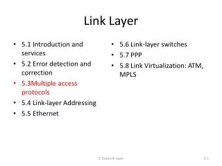
Parity Checking Two Dimensional Bit Parity: Detect and correct single bit errors Single Bit Parity: Detect single bit errors 0 0 Link Layer
1 0 0 1 0 0 0 0 0 0 0 1 1 0 0 1 0 0 1 0 0 1 1 0 1 0 0 1 1 1 1 0 0 1 0 0 0 0 0 0 0 1 1 0 0 1 0 0 1 1 0 1 1 0 1 0 0 1 1 1 Two errors One error 1 0 0 1 0 0 0 0 0 1 0 1 1 0 0 1 0 0 1 0 0 0 1 0 1 0 0 1 1 1 1 0 0 1 0 0 0 0 0 1 0 1 1 0 0 1 0 0 1 0 0 1 1 0 1 0 0 1 1 1 Three errors Four errors (undetectable) Arrows indicate failed check bits Error-detecting capability 1, 2, or 3 errors can always be detected; Not all patterns >4 errors can be detected Link Layer
Internet Checksum • Several Internet protocols (e.g. IP, TCP, UDP) use check bits to detect errors in the IP header (or in the header and data for TCP/UDP) • A checksum is calculated for header contents and included in a special field. • Checksum recalculated at every router, so algorithm selected for ease of implementation in software • Let header consist of L, 16-bit words, b0, b1, b2, ..., bL-1 • The algorithm appends a 16-bit checksum bL Link Layer
Other Error Detection Codes • Many applications require very low error rate • Need codes that detect the vast majority of errors • Single parity check codes do not detect enough errors • Two-dimensional codes require too many check bits • The following error detecting codes used in practice: • Internet Check Sums • CRC Polynomial Codes Link Layer
Internet Checksum • Several Internet protocols (e.g. IP, TCP, UDP) use check bits to detect errors in the IP header (or in the header and data for TCP/UDP) • A checksum is calculated for header contents and included in a special field. • Checksum recalculated at every router, so algorithm selected for ease of implementation in software • Let header consist of L, 16-bit words, b0, b1, b2, ..., bL-1 • The algorithm appends a 16-bit checksum bL Link Layer
Checksum Calculation The checksum bL is calculated as follows: • Treating each 16-bit word as an integer, find x = b0 + b1 + b2+ ...+ bL-1 modulo 216-1 • The checksum is then given by: bL = - x modulo 216-1 Thus, the headers must satisfy the following pattern: 0 = b0 + b1 + b2+ ...+ bL-1 + bL modulo 216-1 • The checksum calculation is carried out in software using one’s complement arithmetic Link Layer
Use Modulo Arithmetic Assume 4-bit words Use mod 24-1arithmetic b0=1100 = 12 b1=1010 = 10 b0+b1=12+10=7 mod15 b2 = -7 = 8 mod15 Therefore b2=1000 Use Binary Arithmetic Note 16 =1 mod15 So: 10000 = 0001 mod15 leading bit wraps around Internet Checksum Example b0 + b1 = 1100+1010 =10110 =10000+0110 =0001+0110 =0111 =7 Take 1s complement b2 = -0111 =1000 Link Layer
Polynomial Codes • Polynomials instead of vectors for codewords • Polynomial arithmetic instead of check sums • Also called cyclic redundancy check (CRC) codes • Most data communications standards use polynomial codes for error detection • Polynomial codes also basis for powerful error-correction methods Link Layer
4 3 quotient dividend = quotient x divisor +remainder 35 ) 1222 dividend 105 1222 = 34 x 35 + 32 divisor 2 17 140 remainder + x = q(x) quotient x3 + x2 x3 + x+ 1 ) x6 + x5 x6 + x4 + x3 dividend divisor x5 + x4 + x3 x5 + x3 + x2 x4 + x2 x4 + x2 + x x = r(x) remainder Binary Polynomial Division • Division with Decimal Numbers 32 • Polynomial Division Note: Degree of r(x) is less than degree of divisor Link Layer
b(x) = xn-ki(x) + r(x) n bits n-k bits k bits q(x) xn-ki(x) = q(x)g(x) + r(x) g(x) ) xn-k i(x) r(x) Polynomial Coding • Code has binary generating polynomial of degree n–k g(x) = xn-k + gn-k-1xn-k-1 + … + g2x2 + g1x + 1 • k information bits define polynomial of degree k – 1 i(x) = ik-1xk-1 + ik-2xk-2 + … + i2x2 + i1x + i0 • Find remainder polynomial of at most degree n – k – 1 • Define the codeword polynomial of degree n – 1 Link Layer
Generator polynomial: g(x)= x3 + x + 1 Information: (1,1,0,0) i(x) = x3 + x2 Encoding: x3i(x) = x6 + x5 x3 + x2 + x 1110 x3 + x+ 1 ) x6 + x5 1011 ) 1100000 x6 + x4 + x3 1011 1110 x5 + x4 + x3 1011 x5 + x3 + x2 1010 x4 + x2 1011 x4 + x2 + x x 010 Polynomial example: k = 4, n–k = 3 Transmitted codeword: b(x) = x6 + x5 + x b= (1,1,0,0,0,1,0) Link Layer
The Pattern in Polynomial Coding • All codewords satisfy the following pattern: b(x) = xn-ki(x) + r(x) = q(x)g(x) + r(x) + r(x) = q(x)g(x) • All codewords are a multiple of g(x)! • Receiver should divide received n-tuple by g(x) and check if remainder is zero • If remainder is nonzero, then received n-tuple is not a codeword Link Layer
Checksumming: Cyclic Redundancy Check • view data bits, D, as a binary number • choose r+1 bit pattern (generator), G • goal: choose r CRC bits, R, such that • <D,R> exactly divisible by G (modulo 2) • receiver knows G, divides <D,R> by G. If non-zero remainder: error detected! • can detect all burst errors less than r+1 bits • widely used in practice (ATM, HDCL, Ethernet) Link Layer
CRC Example Want: D.2r XOR R = nG equivalently: D.2r = nG XOR R equivalently: if we divide D.2r by G, want remainder R D.2r G R = remainder[ ] Link Layer
Hamming Distance • Codeword (TotalCodeLength = ActualData + RedundantInfo) • Hamming Distance = # of bit diff in two codeword • It will need d bits error to convert one codeword to another • Legal codeword and illegal codeword • D bits error detection => Hamming distance (D+1) • D bits error correction => Hamming distance (2D+1) • 0000000000, 0000011111, 1111100000, 1111111111 distance =5 • Can correct any 2 bits errors • Use of a Hamming code to correct burst errors Link Layer
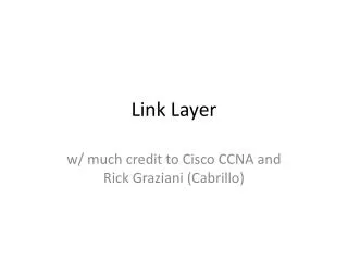
Single Bit Error Correction – Hamming Code 1,2,4,8,16 Link Layer
Generating Hamming Code Link Layer