Download
1 / 13
150 likes | 304 Views
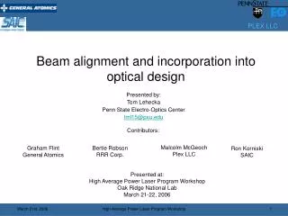
Beam alignment and incorporation into optical design. Presented by: Tom Lehecka Penn State Electro-Optics Center tml15@psu.edu. Contributors:. Malcolm McGeoch Plex LLC. Bertie Robson RRR Corp. Graham Flint General Atomics. Ron Korniski SAIC. Presented at:

E N D
Beam alignment and incorporation into optical design Presented by: Tom Lehecka Penn State Electro-Optics Center tml15@psu.edu Contributors: Malcolm McGeoch Plex LLC Bertie Robson RRR Corp. Graham Flint General Atomics Ron Korniski SAIC Presented at: High Average Power Laser Program Workshop Oak Ridge National Lab March 21-22, 2006 High Average Power Laser Program Workshop
Outline • System layout • Optical performance • Incorporation of the alignment system • Steering mirror performance requirements • Alignment process definition High Average Power Laser Program Workshop
Facility Layout 205 m Single 25 kJ module • Twenty beamline system, one spare amp per side • Modular design with ~ 25 kJ per amplifier High Average Power Laser Program Workshop
Single 25 kJ Module Block Diagram “Front End” • Ninety-eight beams per amp, 90 for target interaction, 8 for backlighters/amplifier loading High Average Power Laser Program Workshop
Amplifier Area Optical Layout Beam from front end. 98 beams total, one shown Input mirror - Convex Rc = -14.54 m 8X8 cm beam Imaging lens Plano-convex Rc = -14.54 m 7X7 cm beam Amp 2 mirror Convex-Rc = 26.6 m 30X30 cm beam Amp 2 Intermediate mirror Flat 13.9X13.9 cm beam Amp 1 mirror Convex-Rc = 68.1 m 100X100 cm beam Amp 1 Recollimation mirror Convex Rc = -22.2 m 16X16 cm beam To Target Final Lens Plano-Convex f = 17 m 16X16 cm beam Demultiplex mirror Flat 16X16 cm beam • Single lens image relay from amp 2 to amp 1. All powered optics spherical • Tilt of imaging lens and final lens corrects for astigmatism introduced at amplifiers • Output beam size of 16x16 cm yields fluence of 1.1 J/cm2 on optics High Average Power Laser Program Workshop
Optical Performance Code V model of worst case beam: Performance w/ imaging lens and final lens tilted RMS Wavefront Error (RMS WFE) is 0.004wave Point Spread Function (PSF), & RMS WFE: Diffraction based Spot Diagram: Geometrically based Airy Disk diameter Diffraction limited performance with simple spherical optics! High Average Power Laser Program Workshop Filename: FTFb8sqTILnFL
Beam Steering Concept • Fast steering mirrors control overlap of outgoing laser beam and incoming target glint High Average Power Laser Program Workshop
Target Chamber Layout Path from lens to target, Straightened out for clarity Dielectric mirrors Lenses GIMM, 15 segments Dielectric mirrors GIMM Fast steering mirror (FSM) Lens Coincidence sensor Wedged mirror • Desire to keep FSM and sensor close to target but well out of neutron irradiation • Potential location for one beam shown High Average Power Laser Program Workshop
Target Tracking Variable definitions: t0: laser on target time tf: time of flight for target from injection to chamber center (O~ 80 ms) tp: laser propagation time from front end to target ts: time required for steering mirror correction of the beam (O~ 1.2 ms) Rs: radial distance of target from R0 at time t0-ts. (Rs=vtarget/ts, O~ 12 cm) R0*: target location at time t0. Will vary each shot R0: chamber center drs: radial correction of beam provided by fast steering mirror (O~ 3 mm) drinj: radial error of target injector (O~ 2 mm) drs drinj Rs Target vtarget Glint laser strikes target at time t0-ts, at a radial location R0-Rs Rs not drawn to scale • Simple statement of the problem is that we must place the target within the correction zone provided by the fast steering mirror drinj<drs (Thanks Bertie!) High Average Power Laser Program Workshop
Beam steering process • Alignment laser is maintained near center of the coincidence sensor using steering mirror • Target is injected at t0-tf • In flight tracking system (Doppler measurement and Poisson spot tracker) determine target trajectory and predict arrival time ts at Rs. • Glint laser fires at time t0-ts • Glint signal is received at coincidence sensor. Target R0* is predicted based on this signal and the known trajectory from step 3 • Fast steering mirror is commanded to position alignment laser to predicted R0*. This location will be a position near the center of the coincidence sensor. TBD if move is made based on alignment laser or position sensors on board the FSM. • Alignment laser fires to verify laser correction on the coincidence sensor. • Main laser fires at time t0-tp. Timing is based on predicted arrival at R0* from measurement of target at Rs and measured velocity. • Laser and target arrive at R0* at time t0. High Average Power Laser Program Workshop
Steering Mirror Correction Times Centroid determination: 100 ms ~ 30 kHz bandwidth Mirror response: Acceleration*: 300 ms 44 mradian = 1.5 mm Deceleration*: 300 ms 44 mradian = 1.5 mm Settling time: 500 ms 0.5% level TOTAL 1.2 ms = ts For vtarget=100 m/s Rs=12 cm • *Calculated for 1000 radian/s2 mirror acceleration and 17 m focal length • Times are adjustable but an increase in the total time will effect system’s insensitivity to vibration • Vibration levels at 833 Hz and above (1.2 ms) are expected to be small High Average Power Laser Program Workshop
Fast Steering Mirror System • Commercially available mirrors meet and exceed requirements with exception of bandwidth and settling time. Alternatively can we increase ts to 2.5 ms? • Bandwidth and settling time will depend on mirror and control system architecture. Input shaping can provide ~10X improvement in performance. This needs experimental verification. High Average Power Laser Program Workshop
Summary • Simple optical imaging in amplifier region provided diffraction limited performance • Potential locations for fast steering mirrors and diagnostics being determined • Commercially available fast steering mirrors are close to the requirements for beam steering onto target – bandwidth and step & settle time need some improvement • Work over the past four months has made all team members believe that tracking, alignment & injection based on current technology is achievable High Average Power Laser Program Workshop