Beam Design
Beam Design. Anything wrong here?. Discussion Topics--Beam Types. 1--Solid timber beam 2--Built-up dimensional lumber beam 3--Glued Laminated beam 4--Parallel strand lumber beam (PSL) 5--Laminated veneer lumber beam (LVL) 6--Truss I-Joist beam 7--Box or Plywood beam


Beam Design
E N D
Presentation Transcript
Discussion Topics--Beam Types • 1--Solid timber beam • 2--Built-up dimensional lumber beam • 3--Glued Laminated beam • 4--Parallel strand lumber beam (PSL) • 5--Laminated veneer lumber beam (LVL) • 6--Truss I-Joist beam • 7--Box or Plywood beam • 8--Flitch beam (wood and steel) • 9--Steel beams
Beam Type—Built-up Dimensional Lumber Beam • Dimensional lumber (2x6, 2x8, 2x10, 2x12) nailed, screwed, and/or glued together • Vertical placement— • Large size placed vertical
Example: Beam and Joist Attached with joist hangers • Joist are attached to beams with metal joist hangers • What type of beam is shown?
Beam Type—Glued Laminated • Dimensional lumber placed horizontally and glued together
Beam Type—Laminated Veneer Lumber Beam • Laminated Veneer Lumber (LVL) • Made of ultrasonically graded douglas fir veneers with exterior adhesives under heat and pressure • 1 3/4” wide x (5 1/2 to 18”) depth
Beam Type—Truss I-Joist Beam • Laminated or Solid wood (top and bottom chords) • OSB or Plywood web
Beam Type—Box or Plywood Beam • 2x @ 12” or 16” structure with plywood skin • Designed by architect or engineer
Beam Type—Flitch Beam • A sandwich of wood and steel • An architect/engineer designed beam
S-- I Shape W or M Shape C- Channel Shape Beam Type—Steel Beams • S shape (American Standard shape) • Often called an I-beam • W & Mshapes • Wide flange design • C shape • Channel shape
SHAPE NOMINAL HEIGHT WEIGHT PER FOOT OF BEAM Beam Type—Steel Beams • Drawing Callouts: • Shape, Nominal height x Weight/foot • Example: W10x25
Reaction • Reactionis the portion of the load that is transferred to the bearing points of the beam • A simple beam reaction to a load would be at the end supports. Each end would support or be required to carryhalf the total load
W = 900 #/ linear foot Span = 10’-0” Span = 15’-0” R1 R3 R2 Calculating the Reactions of a Beam Reaction formula R = wl • Total load on beam should equal reaction loads: • 25 x 900 = 22500# • R1 = 15/2 x 900# = 6750# • R2 = 10/2 x 900# = 4500# • R3 = (15/2 + 10/2) x 900 =11250# 2 W = uniform load l = length of span
Simple Beam Design • Simple beam has a uniform load evenly distributed over the entire length of the beam and is supported at each end. • Uniform load = equal weight applied to each foot of beam.
Tributary area of beam 15’-0” Beam span Simple Beam Design • Terminology • Joist/Rafter • Beam/Girder • Post/Column • Span • Tributary area • Conditions of Design • Uniform load over length of beam • Beam supported at each end
Simple Beam Design • Tributary area • 16’ x 15’ = 240 sq ft • Total Load on Beam • 240 x 50#/sq ft = 12,000# • Load at each supporting end • 12,000/2 = 6000# 15’-0” Tributary area of beam Beam span
Table Design Considerations • Total lbs of load and span • Lbs of load per (lineal) foot • Deflection Allowances (Stiffness) • Floor = 1/360: Meaning an allowance of 1” deflection for every 360” span, structure is solid with little deflection • Roof = 1/240: Meaning an allowance of 1” deflection for every 240” span, structure springs or deflects more than floors
20’-0” BEAM 12’-0” 10’-0” Determine the size of a Solid Wood Beam using Span Table • 1)Determine the tributary area and calculate the total load (W) for the beam, LL = 50#, DL = 13#, therefore TL = 63# 10 x 12 x 63 = 7560 TLD • Select beam size from table
7560 TLD w/ span of 12’ Roof Design Area 1/240 • Solution = 4 x 14 Beam Floor Design Area 1/360
Reading the Steel Table • Table values of load are given in kips • 1 kip = 1000 lbs • Shape and nominal size across the top • Weight per foot is given below designation • Span is located along the left side of table
BEAM 30’-0” 18’-0” • Selected Beam • S18 x 54.7 Example of Using Steel Table • Calculate load: 18 x 30 x 60 = 32400 TLD = 32.4 KIPS
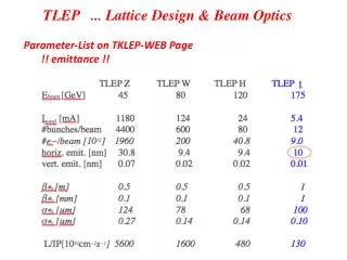
Glued-Laminated Beam Table Design Data: Span 18’, Load per linear feet = 674#
Reading Column Tables • Determine the column load • Establish the height of column • Set the column size by height and load
Steel Column Table Conditions: Height = 4.5’, Load = 19.4 kips Solution: 2 ½ Dia x 5.79 PIPE COLUMN
Wood Post Table Conditions: Height = 4 feet, Load = 23,000 Solution: 4x6 WOOD POST
Load Considerations • First floor loads (DL + LL) = 50#/sq ft • First floor partitions (DL) = 10#/sq ft • Second floor loads (DL + LL) = 50#/sq ft • Second floor partitions (DL) = 10#/sq ft • If Truss design no loads on interior structure(DL) • If rafter/ceiling joist design (DL) = 20#/sq ft • Roof load regionally varies (LL) = 20-50#/sq ft
Beam Sizing and Post Spacing Trial & Error Method 1--Locate tributary area 2--Determine various conditions placing post to shorten the beam span 3--Go to tables & choose beam 4--Smaller beams are less expensive and usually better
Handout on Structural Analysis #2 • Before doing calculations sketch problem to visualize conditions • Calculate the tributary loads for beams and columns conditions • Use Handout charts and tables and select beams and columns for conditions