Download
1 / 24
240 likes | 585 Views
Learn about geometric parameters essential for highway design speed, including stopping sight distance, horizontal curvature, and vertical crest curves. Explore relaxation and departure tiers to minimize construction costs and environmental impacts.

E N D
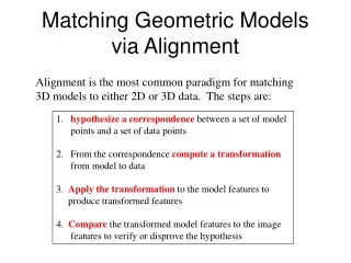
Geometric parameters dependent on design speed • For given design speeds, designers aim to achieve at least the desirable minimum values for stopping sight distance, horizontal curvature and vertical crest curves. • However, there are circumstances where the strict application of desirable minima would lead to disproportionately high construction costs or environmental impact • Two lower tiers can be employed: • Relaxations • Departures.
Relaxations • This second tier of values will produce a level of service that may remain acceptable and will lead to a situation where a highway may not become unsafe. • The limit for relaxations is defined by a set number of design speed steps below a benchmark level – usually the desirable minimum (TD 9/93).
Departures • In situations of exceptional difficulty where even a move to the second tier in the hierarchy, i.e. relaxations, cannot resolve the situation, adoption of a value within the third tier of the hierarchy – a departure – may have to be considered. • In order for a departure from standard to be adopted for a major road scheme, the designer must receive formal approval from central government or its responsible agency before it can be incorporated into the design layout.
Sight distances • Sight distance is defined as the length of carriageway that the driver can see in both the horizontal and vertical planes. • Two types of sight distance are detailed: • stopping distance • overtaking distance.
Stopping sight distance • This is defined as the minimum sight distance required by the driver in order to be able to stop the car before it hits an object on the highway. • Primary importance to the safe working of a highway • The standard TD 9/93 requires stopping sight distance to be measured from a driver’s eye height of between 1.05m and 2m above the surface of the highway to an object height of between 0.26m and 2m above it.
Stopping sight distance • The vast majority (>95%) of driver heights will be greater than 1.05m while, at the upper range, 2m is set as the typical eye height for the driver of a large heavy goods vehicle.
The distance itself can be subdivided into three constituent parts: • The perception distance – length of highway travelled while driver perceives hazard • The reaction distance – length of highway travelled during the period of time taken by the driver to apply the brakes and for the brakes to function • The braking distance – length of highway travelled while the vehicle actually comes to a halt.
Perception-reaction distance (m) = 0.278tV where V = initial speed (km/hr) t = combined perception and reaction time (s) – usually 2s • Braking distance (m) = v 2 /2w where v = initial speed (m/s) w = rate of deceleration (m/s 2 )
Overtaking sight distance • Overtaking sight distance only applies to single carriageways • There is no full overtaking sight distance (FOSD) for a highway with a design speed of 120km/hr since this design speed is not suitable for a single carriageway road.
Full overtaking sight distance is measured from vehicle to vehicle (the hazard or object in this case is another car) between points 1.05m and 2.00m above the centre of the carriageway.
Full overtaking sight distance is made up of three components: d1, d2, and d3 • d1 = Distance travelled by the vehicle in question while driver in the overtaking vehicle completes the passing manoeuvre (Overtaking Time) • d2 = Distance between the overtaking and opposing vehicles at the point in time at which the overtaking vehicle returns to its designated lane (Safety Time) • d3 = Distance travelled by the opposing vehicle within the above mentioned ‘perception-reaction’ and ‘overtaking’ times (Closing Time).
In order to establish the values for full overtaking sight distance, it is assumed that the driver making the overtaking manoeuvre commences it at two design speed steps below the designated design speed of the section of highway in question. The overtaking vehicle then accelerates to the designated design speed. • During this time frame, the approaching vehicle is assumed to travel towards the overtaking vehicle at the designated design speed. d2 is assumed to be 20% of d3.
FOSD = 2.05tV where V = design speed (m/s) t = time taken to complete the entire overtaking manoeuvre (s) • The value of t is generally taken as 10 seconds, as it has been established that it is less than this figure in 85% of observed cases.
If we are required to establish the FOSD for the 85th percentile driver on a section of highway with a design speed of 85km/hr (23.6m/s), we can use: • FOSD 85 = 2.05 x 10 x 23.6 • = 483.8m • If we go back to the three basic components of FOSD, d1, d2, and d3, we can derive a very similar value: • d1 = 10 seconds travelling at an average speed of 70km/hr (19.4m/s) = 10 x 19.4m = 194m • d3 = Opposing vehicle travels 10 x 23.6m = 236m • d2 = d3/5 = 47.2m • FOSD = 194 + 236 + 47.2 = 477.2m
Horizontal alignment • Horizontal alignment deals with the design of the directional transition of the highway in a horizontal plane • A horizontal alignment consists, in its most basic form, of a horizontal arc and two transition curves forming a curve which joins two straights. • Minimum permitted horizontal radii depend on the design speed and the superelevation of the carriageway, which has a maximum allowable value of 7% in the UK, with designs in most cases using a value of 5%.
The minimum radii permitted for a given design speed and value of superelevation which should not exceed 7%.
Forces on a vehicle negotiating a horizontal curve • (Weight of vehicle resolved parallel to highway) + (Side friction factor) = (Centrifugal force resolved parallel to highway)
The angle of incline of the road (superelevation) is termed a. • P denotes the side frictional force between the vehicle and the highway, and N the reaction to the weight of the vehicle normal to the surface of the highway. • C is the centrifugal force acting horizontally on the vehicle and equals M = v 2 /R where M is the mass of the vehicle.
[Mg x Sin(α)] + P = [(M x v 2 /R) x Cos (α)] • P = μ[W x Cos(α) + C x Sin(α) • = μ[Mg x Cos(α) + M x v2/R x Sin(α) • (μ is defined as the side friction factor) • tan(α ) + μ= v 2/gR • The term tan(α) is in fact the superelevation, e. If in addition we express velocity in kilometres per hour rather than metres per second, and given that g equals 9.81m/s 2 , the following generally used equation is obtained:
Therefore, assuming e has a value of 5% (appropriate for the desirable minimum radius R): • R = 0.07069V 2 • Taking a design speed of 120km/hr: • R = 0.07069(120) 2 • = 1018m