Download
1 / 22
220 likes | 361 Views
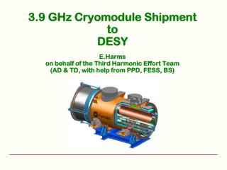
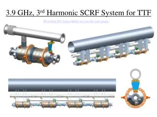
3.9 GHz Harmonic Linearizer. Elvin Harms LCLS-II Accelerator Physics Meeting 9 April 2014. Introduction. ACC39 at FLASH Proposal for LCLS-II LH Parameters Assumptions Summary. Harms, LCLS-II Accelerator Physics 9 Apr 2014. The Linearizer module - What is it, What does it do ?. 3.

E N D
3.9 GHz Harmonic Linearizer Elvin Harms LCLS-II Accelerator Physics Meeting 9 April 2014
Introduction • ACC39 at FLASH • Proposal for LCLS-II LH • Parameters • Assumptions • Summary Harms, LCLS-II Accelerator Physics 9 Apr 2014
The Linearizer module - What is it, What does it do? 3 Harms, LCLS-II Accelerator Physics 9 Apr 2014 The 3.9 GHz module, ACC39, is installed in the DESY FLASH injector just after the 1.3GHz ACC1 (first) cryo module. It is used in conjunction with ACC1 in order linearize the bunch energy vs. time over the bunch length. This in turn makes “bunch compression” to very short bunches with high peak currents more efficient, or a more controlled longer bunch charge distribution.
Bunch Compression with 3.9 GHz Module After acceleration w/o After compression w/o Short bunch Flat bunch ~250 fs From M Dohlus et al With 3rd harmonic From P Piot 4 Harms, LCLS-II Accelerator Physics 9 Apr 2014
Test Results 5 Harms, LCLS-II Accelerator Physics9 Apr 2014 • Entire cryomodule was first tested at DESY in their CryoModule Test Bench (CMTB) prior to installation in FLASH • Successful assembly • Successful transatlantic shipment • Some rework at DESY • Longitudinal realignment • Instrumentation terminations
ACC39 Performance 6 Harms, LCLS-II Accelerator Physics 9 Apr 2014 Set up for lasing has gone from expert tune up (shifts) to nearly immediate after turn-on
ACC39 Performance 7 Harms, LCLS-II Accelerator Physics 9 Apr 2014 • ACC39 routinely operates at 18.9 to 19.7 MV/m • Capable of operation at 22 MV/m • Limitation set by thermal interlocks – concern about compromising HOM’s on Cavities 3 & 5 (trimmed 2-post style) • Amplitude stability ≤ 2x10⁻⁵ pulse-to-pulse • Phase stability ≤ 0.003° pulse-to-pulse
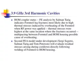
Experiences & Lessons Learned (and applied) • New infrastructure had to be built • Commissioning in parallel with qualifying components • Vertical test stand • Horizontal Test Stand • Coupler Conditioning • Clean rooms • … • HOM redesign • Not simply a scaled version • Modeling and prototyping important • Robust design is the end result • HOM coupler antennae • Prototyping and testing is vital before placing order • Engineering Notes & Operational Readiness Clearance • Transatlantic Transport of a complete cryomodule • Welding certification • Especially Helium vessels • ‘New’ technologies explored and applied Harms, LCLS-II Accelerator Physics 9 Apr 2014
Looking Ahead – CW Operation • Heat Load/Cryogenic piping • Limit total cryomodule heat load to <250 watts • Dynamic Heat Load needs to be revisited • Estimated heat load ~15 watts/cavity @ 15 MV/m • Input coupler power capability/cooling • Current design should be good to ~2kW cw, but needs to be re-analyzed • Studies are possible using coupler stand at A0 with a cw amplifier • Is a variable coupler necessary rather than current ‘fixed’ design Harms, LCLS-II Accelerator Physics 9 Apr 2014
Looking Ahead – CW Operation (2) • HOM coupler and feedthroughcapability • Current (single-post) ‘Formteil’ design • multi-pacting lower bound ~25 MV/m • Feedthrough – adequate cooling? • Simulation needed to look at modes (THz?) present in the ends • Absorbing material needed in beam pipe? • Preliminary simulations begun • Microphonics/Fast tuning • Current tuner is slow (blade) tuner only • Cavities are already fairly stiff – resistant to microphonics/LFD • Consider addition of fast/piezo’s or passive microphonics compensation Harms, LCLS-II Accelerator Physics 9 Apr 2014
Looking Ahead – CW Operation (3) • Cavity Global thermal limit is estimated to be of order 25 MV/m • Alignment • Offset = HOM power considerations • Tilt = transverse emittance implications • Other issues to consider • Beam diagnostics, especially internal to module • Quads, dipoles • Cryogenic and vacuum interconnectability to adjacent components • Standalone vs. Integrated module Harms, LCLS-II Accelerator Physics 9 Apr 2014
LCLS-II Layout P. Emma, L. Wang, C. Papadopoulos M. Ross E. Harms APT Seminar 14 January 2014 Harms, LCLS-II Accelerator Physics 9 Apr 2014
Proposed Parameter Set E. Harms APT Seminar 14 January 2014 Harms, LCLS-II Accelerator Physics 9 Apr 2014
3.9 GHz Section Assumptions - 1 • Cryomodule • 8 cavities per Cryomodulewith 2 Cryomodules • Total heat load ~200 W / cryomodule • No magnet, corrector, or BPM’s in 3.9GHz CM’s • Magnets/Quad/BPM will be downstream in warm section • Cavities spaced for Q0 > 2e9 • Beam pipe tapering from 1.3 GHz CM to 3.9 GHz CM • Length of interconnection (distance between CM’s) is free • no requirements in term of wavelength. • Larger diameter 2-phase pipe/nozzle akin to 1.3 GHz • will provide additional cooling than existing design • Cryointerface will be CM2/3 upstream and 'standard' feedbox immediately downstream • Design of cryomodule will strive to bring all signal cables out on the aisle side • Cryomodulewill be cooled with the proposed 2nd cryoplantcapable of ~1kW at 2K along with the other upstream (non-main Linac) CM’s • Cavity-to cavity distance is short (as in FLASH) • HOM (beam pipe) absorber likely placed between two 3.9 GHz CM’s E. Harms APT Seminar 14 January 2014 Harms, LCLS-II Accelerator Physics 9 Apr 2014
3.9 GHz Section Assumptions - 2 • Cavities • Capable of 14.5 MV/m cw • Power dissipation ~17 W / cavity, maximum HOM power ~13 W / CM or 1.6 W / cavity • (>50% will dissipated at 70K or RT) • Blade tuner design with 3 piezosincorporated. • HOM coupler signals may be used for beam offset measurements • Consider modest Q0 improvement development program (N2 doping), but low priority and is not project critical • 1- and 9-cell cavities are available for processing & testing E. Harms APT Seminar 14 January 2014 Harms, LCLS-II Accelerator Physics 9 Apr 2014
3.9 GHz Section Assumptions - 3 • Couplers • Cavity orientation for placement downstream and every second rotated by 180° • Dig tunnel wall if necessary to make room for coupler clearance • “not out of the question” • Waveguide from back side of CM will be pre-assembled and extend to top of CM for connection • Two options for klystron to CM feed: Waveguide or coax • WG option is preferable • coax is lossier, possible center conductor heating • Coupler will require modifications for CW regime • Fixed coupling (Q~1.e7) looks OK. E. Harms APT Seminar 14 January 2014 Harms, LCLS-II Accelerator Physics 9 Apr 2014
Coupler Orientation Options Arun Saini, N. Solyak FermilabCryomodule Layout: XFEL Cryomodule Layout: Goal 1.30 GHz Start here FLASH Cryomodule Layout: E. Harms APT Seminar 14 January 2014 Harms, LCLS-II Accelerator Physics 9 Apr 2014
Coupler Orientation Summary Beam optics through harmonic section is studied. • Fermilab configuration • XFEL Configuration • ILC type cryomodule Coupler RF kick results in significant emittance growth. Local compensation of coupler kick is possible and emittance dilution can be minimized using different orientations of alternative cavity. • XFEL configuration provides best solution in terms of emittance compensation. Goal 1.30 GHz Start here Arun Saini, N. Solyak E. Harms APT Seminar 14 January 2014 Harms, LCLS-II Accelerator Physics 9 Apr 2014
3.9 GHz Section Assumptions - 4 • Testing • Test cavities in VTS and HTS (subset) • maybe ANL/Ostroumov team will do horizontal testing • Cryomoduleswill be cooled down and tested prior to transport to SLAC • 3 kW cw 3.9 GHz in hand – needs to be made operational • 3.9 GHz Infrastructure exists (or can be modified) to do most testing • cavities • couplers • cryomodules E. Harms APT Seminar 14 January 2014 Harms, LCLS-II Accelerator Physics 9 Apr 2014
3.9 GHz Section Actions & Dates • Actions • Will try to start from XFEL CM design --> (Elvin and Tom) • May want to run cavities in pairs to compensate coupler kicks - not clear that this is necessary (Arun to evaluate) • Andrei is evaluating wakefields but expect them to be small • Need to specify alignment tolerances (Arun to evaluate) • Need to test new 3.9 GHz FPC in CW operation --> (need schedule) • In addition to testing FPC new design, task force needs to be formed to look at and review design • Key Dates • 1 June 2014: FRS submitted • 6 October 2014: Design Review E. Harms APT Seminar 14 January 2014 Harms, LCLS-II Accelerator Physics 9 Apr 2014
Summary • 3.9 GHz (pulsed) operating at FLASH • XFEL building a similar module • Technology can be applied for LCLS-II • Issues related to cw operation identified - manageable • Parameter list compiled – needs to be verified • List of assumptions and actions for LCLS-II LH compiled • Simulation/modeling work begun • Coupler design and orientation • Effort needs further formalization • Do as much work as possible now Harms, LCLS-II Accelerator Physics 9 Apr 2014
Thanks Harms, LCLS-II Accelerator Physics 9 Apr 2014