Download
1 / 14
150 likes | 179 Views
This presentation discusses the design considerations for a cryomodule operating in continuous wave (CW) mode at a frequency of 3.9 GHz. Topics include coupler heating concerns, power coupler design, main coupler modifications, thermal simulations, and HOM coupler design. Key information is provided from the presentation slides by Nikolay Solyak and his team.

E N D
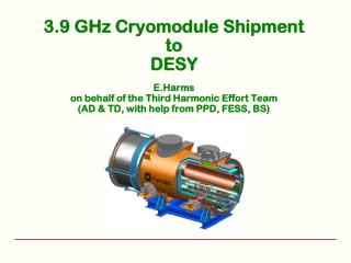
Cryomodule Design for CW Operation3.9 GHz considerations E. Harms on behalf of the Fermilab LCLS-II Cryomodule Design Team TTC meeting at TRIUMF Working Group 4 Session 4 7 February 2019
Introduction • Coupler heating a significant concern in cw regime compared to pulsed operation • 3.9 GHz for LCLS-II an example • Nikolay Solyak, et al source of information in succeeding slides Harms - CW Cryomodule Design| TTC 7 Feb 2019
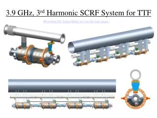
3.9 GHz at LCLS-II • Two 8-cavity cryomodules • 16 MV/m nominal gradient, 41 MV/cryomodule • 3rd generation design • FLASH (4-cavity built by Fermilab) • XFEL (8-cavity built by LASA/DESY) Harms - CW Cryomodule Design| TTC 7 Feb 2019
3.9 GHz power coupler for LCLS-II CW operation • Fix coupling; Q=2.7e7 (2.4e7-3.e7) • Cylindrical cold window (as 1.3GHz) • Waveguide warm window • XFEL/FNAL coupler for pulse operation (Pmax= 45kW, DF=1.3%: Pavrg < 0.6 kW). • LCLS-II: Pmax= 1.8 kW cwin quasi – TW regime: • Tmax ~1000K w/o modification (warm part inner conductor Cu plating 30um) Harms - CW Cryomodule Design| TTC 7 Feb 2019
LCLS-II Main Coupler Design (modification from XFEL design) • 1. Cold part (upper picture) • Dimensions of ceramic window • Length of antenna (QL=2.7e7 vs.1.5e7) • Material of antenna - copper (vs. SS) • => Reduce antenna heating and Qext variation (HTS result) • 2. Warm outer part No changes • 3. Inner conductor of warm section • Cu plating increased from 30 to 150 um. • Convolutions in inner conductor bellows reduced from 20 to 15 • 3 existing warm sections rebuilt to prototype: Tested at RT, power tests, HTS Cold part Warm part (outer conductor) Warm part (inner conductor) and WG box with warm window Harms - CW Cryomodule Design| TTC 7 Feb 2019
HTS 3.9 GHz system Integration test - coupler thermometry HTTP6 HTTX30 HTTXM4 HTTX29 Hardware: Cavity - 3HRI03 Coupler #2, antenna trimmed to 43.1 mm QL (RT) = 1.54e+7 QL(2K /static) = 1.70e+7 QL(2K/dynam)= 1.05e+7 1kW SW Coupling depends on RF power (due to antenna heating). Copper antenna (vs. SS) will fix that problem Harms - CW Cryomodule Design| TTC 7 Feb 2019
Thermal simulations: Effect of antenna material, Copper vs. SS Antenna: SS+50 μm Cu covered / Solid copper Parameters:Pin= 1 kW SWON-resonance:10μm outer plating, ε=9.8, tan=3e-4, roughness 10: warm inner: 120 μm Cu coating of SS inner conductor, 15 bellow conv. TIR ~ 411/430 K HTS: 150K (CM: 110 K) 320K Tmax~ 469/475 K 10K short Port: 1kW Tant = 481/183 K Temperature distribution along inner conductor vs. Z Harms - CW Cryomodule Design| TTC 7 Feb 2019
Coupler assembled at Cavity and Tested at HTS 0.8 kW SW, OFF-resonance 0.8 kW, SW, ON-resonance TCT100~167K PRF=0.8 kW CT flange~160K IR~390K TIR~385K ΔTbraid T80K_shield Expected maximum Temperatures in CM: • <130K at 50K flange – (from 170K at HT) • <400K at inner conductor bellows (from <420K at HTS) Note: HTS uses LN2 line (90K) vs. CM He line (40K), all T related to this line will be by ~40K lower in CM Harms - CW Cryomodule Design| TTC 7 Feb 2019
Thermal simulation summary Temp.boundaries:10/150/320 K; RF power = 1kW, SW. w/o thermal radiation *Confirm at HTS test Copper antenna reduce temperature at tip and provides smaller Qextdeviation in dynamic regime to compare with SS antenna Harms - CW Cryomodule Design| TTC 7 Feb 2019
Temperature and power dissipation at 5K flange 392K > 387K Forward power (W) Note: expected Tmax (inner conductor bellow) ~20K above IR meas. (simul). 5K – end. Cryo heat load Pstatic= 0.7W; Pdyn (on/off)= 1.9/1.6W; OFF-resonance ON-resonance Pdyn (on/off)= 14/12 W; ~ 12W ~14W Measured Power flux Braid temp gradient 80 K – end. ΔT=HTTX30-HTTX29 Temperature, K Infra-red sensor Temperature (inner conductor, warm part) Harms - CW Cryomodule Design| TTC 7 Feb 2019
Thermal intercept design in 3.9GHz CM Coupler uses same straps as in 1.3GHz cryomodule • power flux less than in 1.3GHz coupler • same straps are used as for 1.3GHz system (L~150mm, S=120mm2; 0.29 W/K) Harms - CW Cryomodule Design| TTC 7 Feb 2019
Main Coupler Summary • Three coupler prototypes (warm part) were built and tested: • QC inspection and RF measurements • 2 couplers were HP processed at warm test stand at 2kW cw. • 1 assembled on dressed cavity and tested in HTS at 1kW SW (integrated system test) • Thermal design verified in HTS test and incorporated in CM design. • Coupler procurement in progress (8 couplers are received) Harms - CW Cryomodule Design| TTC 7 Feb 2019
HOM coupler design LCLS-II modified XFEL (INFN/FNAL) design to reduce risks of tuning and heating problems in CW operation. • Reduce beam pipe and bellow diameter from 40 to 38mm to move trapped parasitic mode away to improve the tuning of HOM notch frequency. • Modification of HOM coupler to reduce heating • F-part modification less penetration of antenna inside HOM to reduce heating • Increase wall thickness of HOM hat to 1.3mm to prevent cracks and vacuum leak • Shorter length of HOM feedthrough antenna (Fermilab vs. XFEL) • In XFEL design lowest mode are closer to operation node (min ~10-20 MHz vs. 100MHz in simul.) • beam pipe aperture 38 mm allows to detune the HOM by ~ 100 MHz up. Harms - CW Cryomodule Design| TTC 7 Feb 2019
HOM F-part modification to reduce antenna heating Reduce penetration to beam pipe. Increase length of bump in F-part XFEL/FLASH LCLS-II design G = 3.2e8 G = 1.74e9 • A. Lunin/khabiboulline • Current design HOM antenna quenches at ~20 MV/m in VTS. Expected that quench limit will even lower in CW regime at HTS and CM. • RF power dissipation on HOM antenna reduced by factor of 5.4 after modification Harms - CW Cryomodule Design| TTC 7 Feb 2019