Download
1 / 65
650 likes | 677 Views
Discover the latest advancements in Plasma Focus Fusion Studies by S. Lee and S.H. Saw. Delve into experimental results, scaling laws, and beyond saturation numerical experiments. Learn about the Present and next-generation devices and measurements required. Explore how matter transforms into plasma emitting radiation, depending on temperature and atomic species. Uncover the mechanism of plasma production, advantages of Plasma Focus (PF), and high-power radiation emitted from PF devices. Explore the historical background, modern status, and global presence of PF facilities. This presentation highlights the cutting-edge research and future directions in Plasma Focus Fusion Studies.

E N D
Latest Trends in Plasma Focus Fusion Studies S Lee & S H Saw Institute for Plasma Focus Studies INTI University College, Malaysia Turkish Atomic Energy Authority, Saraykoy Nuclear Research Training Center Ankara 1 October 2009- 2.30 pm
Plan of Talk • Present generation of Plasma Focus devices • Experimental results • Failure of Scaling Laws • Beyond saturation Numerical Expts • Development of next generation devices also requires next generation measurements-Scholz ICDMP
When matter is heated to high temperatures: • It ionizes and becomes a plasma; emitting radiation • Emission spectrum depends on temperature (T) and the atomic species • Generally, the higher T and density n, the more intense the radiation • Depending on heating mechanisms, beams of ions and electrons may also be emitted • In Deuterium, nuclear fusion may take place, if n & T are high enough; neutrons are also emitted. • Typically T> several million K; & compressed n: above atmospheric density.
One method: electrical discharge through gases. • Heated gas expands, lowering the density; making it difficult to heat further. • Necessary to compress whilst heating, to achieve sufficiently intense conditions. • Electrical discharge between two electrodes produces azimuthal magnetic field which interacts with column of current; giving rise to a self compression force which tends to constrict (or pinch) the column. • To ‘pinch’ a column of gas to atmospheric density at T~ 1 million K, a rather large pressure has to be exerted by the pinching magnetic field. • Electric current of hundreds of kA required, even for column of radius of say 1mm. • Dynamic pinching process requires current to rise very rapidly, typically in under 0.1 microsec in order to have a sufficiently hot and dense pinch. • Super-fast, super-dense pinch; requires special MA fast-rise (nanosec) pulsed-lines; Disadvantages: conversion losses and cost of the high technology pulse-shaping line, additional to the capacitor.
Superior method for super-dense-hot pinch: plasma focus (PF) • The PF produces superior densities and temperatures. • 2-Phase mechanism of plasma production does away with the extra layer of technology required by the expensive and inefficient pulse-shaping line. • A simple capacitor discharge is sufficient to power the plasma focus.
THE PLASMA FOCUS The PF is divided into two sections. Pre-pinch (axial) section: Delays the pinch until the capacitor discharge approaches maximum current. The pinch starts & occurs at top of the current pulse. Equivalent to driving the pinch with a super-fast rising current; without necessitating the fast line technology. The intensity which is achieved is superior to even the super fast pinch.
Two Phases of the Plasma Focus Axial Phase Radial Phase
Plasma Focus Devices in Singapore The UNU/ICTP PFF (UnitedNationsUniversity/International Centre for Theoretical Physics Plasma Focus Facility) • 15 kV, 3kJ • single-shot, portable; 170kA • 3J SXR per shot (neon) • 108 neutrons/ shot (in D2) • 1016 neutrons/s (estimated) (This device is also in operation in Malaysia, Thailand, India, Pakistan, Egypt, Zimbabwe) 1m
NX2-Plasma SXR Source • NX2 • 11.5kV, 2 kJ • 16 shots /sec; 400 kA • 20J SXR/shot (neon) • 109 neutrons/shot (est)
Small PF, high rep rate for materials interrogation applications • Pulsed neutron source, 'fast miniature plasma focus (PF) device‘- first step in develooment • Neutron yield 106 neutrons/shot ~80 kA, 2 mbar. • Strong pinching action, hard x-rays followed by a neutron pulse; • measured by 3He proportional counter, NE102A plastic scintillator and CR-39 SSNTDs). • 0.2 m × 0.2 m × 0.5 m ~25 kg.
High Power Radiation from PF Powerful bursts of x-rays, ion beams, REB’s, & EM radiation (>10 gigaW) Intense radiation burst, extremely high powers E.g. SXR emission peaks at 109 W over ns In deuterium, fusion neutrons also emitted
Introduction PF: independently discovered by N.Filippov and J.Mather in the mid 50s – early 60s. Filippov-typeMather-type 1 – anode, 2 – cathode, 3 – insulator, 4 – vacuum chamber, С – power supply, L – external inductance, S – spark gap. I – break-down phase; II – run-down phase; III – dense plasma focus phase
Modern Status Now PF facilities (small to big) operate in Poland (PF-1000 and PF-6 in IPPLM, PF-360), Argentina, China, Chile, Great Britain, India, Iran, Japan, Mexico, Korea, Malaysia, Pakistan, Romania, Singapore, Thailand, Turkey, USA, Zimbabwe etc. This direction is also traditional for Russia: Kurchatov Institute (PFE, 180 kJ and biggest in the world facility PF-3, 2.8 MJ), Lebedev Institute (“Tulip”, PF-4), MEPhI, Sarov, ITEF (PF-10)- from V.I. Krauz
1997 ICDMP (International Centre for Dense Magnetised Plasmas) Warsaw-now operates one of biggest plasma focus in the world, the PF1000
PF-1000, IPPLM, Warsaw • Vacuum chamber ~ 3.8 m3 • = 1.4 m, L = 2.5 m • Anode diameter is 226 mm • Cathode diameter is400 mm • Cathode consists of 24 rods • (32 mm in diameter) • Anode length is 560 mm • Insulator length is 113 mm Charging voltage - U0 = 20 - 40 kV, Bank capacitance - C0 = 1.332 mF, Bank energy - E0 = 266 - 1064 kJ, Nominal inductance - L0 = 15 nH, Quarter discharge time - T/4 = 6s, Short-circuit current – ISC = 12 MA, Characteristic resistance - R0 = 2.6 m, Main goal – studies on neutron production at high energy input Presented by M.Scholz, IPPLM
An interesting trend-Numerical Experiments using Lee model code to benchmark Diagnostics Once the computed current trace is fitted to the Measured Current, the numerical experiment and the laboratory experiment are mass and energy compatible; & computed properties are realistic. Model is an Universal Numerical Machine
Computed Properties of the PF1000: Currents, tube voltage, trajectories, speeds, energy distributions, temperatures, densities, SXR power and neutron yield
Plasma Focus PF-3 • Filippov’s-type • Anode Diameter = 1 m • Chamber Diameter=2,5 m • Cathode - 48 rods; diameter = 115 cm Distance between anode and upper = 10 cm • Height of the insulator = 14 cm • Maximal energy (Cmax=9,2 mF, Vmax=25 kV) is 2,8 MJ • Short-circuit current =19 MA • Current on the load - up to 4 MA at 1MJ Built in 1983 Main direction of activity - Search of new ways of PF performance and applications. E.g. use PF as a driver for magnetic compression of liners
PF-3 Experimental Setup- with plasma producing substances Experiments with various plasma-producing substances & various filling gases were recently the main content of activities at the PF-3 facility Vacuum lock developed for delivery of liners to compression zone. 1 – anode; 2 – cathode; 3 – insulator; 4 – plasma current sheath; 5 – anode insertion; 6 – suspension ware; 7 – liner; 8 – loading unit with a vacuum lock; 9, 10 – diagnostics ports; PF discharge chamber
Plasma focus as a driver for magnetic compression of liners Some combined schemes are discussed for production of laboratory soft X-ray sources, where PF is used as inductive storage and the current sheath realizes energy transport to the load located at the system axis. Due to spatial-temporal current peaking it is possible to achieve current rise rate on the load İ ~ I (Vr / ) ~ 1014 A/s at I ~ 3 MA, ~ 1 cm & Vr ~ 3107 cm/c The prospects of such an approach has been shown first in the Polish-Russian experiment on the foam liner compression at PF-1000 facility: M.Scholz, L.Karpinski, W.Stepniewski, A.V.Branitski, M.V.Fedulov, S.F.Medovstchikov, S.L.Nedoseev, V.P.Smirnov, M.V.Zurin, A.Szydlowski, Phys.Lett., A 262 (1999), 453-456 Main problem: the efficiency of the energy transfer to the load
Experiments with liners Long radial compression duration (~ 10s) : preliminary heating of the target and, subsequently, acceleration of the initially – condensed material into plasma state is attained. wire array 0.66 mg/cm Ip = 1.2 MA foam liner 0.3 mg/cm Ip = 1.2 MA foam liner 0.3 mg/cm Ip = 2.5 MA foam liner 1.0 mg/cm Ip = 2.5 MA Diameter of the foam liner at the moment of the contact with the sheath exceeds the initial diameter– pre-heating by the sheath radiationTherefore, PF discharge can effectively control process of liner evaporation and ionisation by changing the gas and the liner parameters; thus assists in overcoming “cold start” problem.
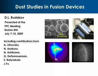
Experimental set-up– Dust Target Dust target produced at system axis as a freely-falling flow of fine-dispersed (2 - 50 mm) powder of Al2O3 1 – anode; 2 – cathode; 3 – insulator; 4 – central anode insert; 5 – plasma-current sheath; 6 – pinch; 7 – dust column; 8 – vacuum lock; 9 – shaping drifting tube; 10 – tank with powder; 11 – electromagnet; 12, 13 – diagnostic ports
KPF-4 (“PHOENIX”), SPhTI, Sukhum Capacitive storage (left) and discharge chamber with current collector (right) Wmax= 1.8 MJ, Vmax=50 kV, discharge system – Mather-type outer electrode – 300 mm diameter (36 cooper rods, 10 mm in diameter) inner electrode (anode) – 182 mm diameter, 326 mm in length insulator – alumina, 128 mm in diameter, 50-100 mm in length Discharge dynamics has been studied at energy supply up to 700 kJ and discharge currents 3-3.5 МА Main goal – development of powerful neutron and X-ray source for applications. (E.A.Andreeshchev, D.A.Voitenko, V.I.Krauz, A.I.Markolia, Yu.V.Matveev, N.G.Reshetnyak, E.Yu.Khautiev, 33 Zvenigorod Conf. on Plasma Phys. and Nuclear Fus., February 13-17, 2006, Zvenigorod, Russia)
Plasma-wall interaction simulation for thermonuclear reactor experiments • D-plasma jets (1 keV) and fast ion beams (50-150keV) generated in the PF was used to bombard low-activated austenitic steel 25Cr12Mn20W and ferrite steel 10Cr9W positioned in cathode part of PF chamber. PF beam conditions was suitable for reactor first wall material testing, during the PF short burst. • ERDA (Elastic Recoil Detection Analysis) was used to trace D scattering profile within irradiated samples
Some conclusions of plasma-wall interaction using PF • When power flux density of irradiation was 106-108 W/cm2. ion implantation to irradiating material surface layer is observed • When power flux density increases to 109 W/cm2 , so-called ‘broken-implantation” takes place • Ion diffusion velocity of implanted deuterium through both interfaces-’layer-bulk material’ and ‘layer-gas phase’ for Fe-based alloys were estimated.
International Collaboration • Plasma Focus • is a very cost effective experimental set-up • Multitude of physical phenomena • Many applications • PF is used successfully as facilities for scientific collaboration • Asian African Association for Plasma Training • International Centre for Dense Magnetised Plasmas
UNU/ICTP Training Programmes AAAPT ACTIVITIES Abdus Salam with UNU Plasma Focus Trainees, Kuala Lumpur, 1986
IAEA Co-ordinated Research Programme IAEA Co-ordinated Research Project “Dense Magnetized Plasma” joins 12 institutions from 8 countries: Poland, Russia, Italy, Singapore, China, Estonia, Romania, Republic of Korea. The main directions of applications developed are: • radiation material science; • proton emission tomography; • X-ray lithography; • radiation enzymology; • radiation medicine, etc; (Proceedings of the 2nd IAEA Co-ordination Meeting of the Co-ordinated Research Project on Dense Magnetized Plasma, 1-3 June 2005, Kudowa Zdroj, Poland, Nukleonika 2006; 51(1))
Neutron Scaling: from optimism up to disappointment • Essential progress was achieved in the early 2-3 decades in the understanding physical processes in PF. • One of the most important achievement was empirical scaling for neutron output: N~E2 or N~I4 • All attempts to reach 1013 D-D neutrons expected for 1 MJ were failed • The best result achieved till now is ~ 1012 at W~500 kJ (Los-Alamos, Limeil, Frascati) • As a result PF activities were shut down in many countries – leaders in fusion researches Neutron yields N against energy E, assembled by H.Rapp (Michel L., Schonbach K.H., Fisher H. Appl. Phys. Lett.- 1974.-V.24, N2.-P.57-59)
Illustrating Yn ‘saturation’ observed in numerical experiments (solid line) compared to measurements on various machines (small squares)
Small PF-400J; 0.4kJ 28 kV 6.6 Torr D2 ~300ns risetime; ~ 20ns current dip of <5% End axial speed: 10cm/us Large PF1000 (0.5 MJ) 27 kV 3.5 Torr D2 ~8 us risetime; ~2 us current dip of 35% End axial speed: 10cm/us Comparing Itotal for small & large plasma focus
Yn saturation trend already observed in numerical experiments • The deterioration of the Yn scaling observed in numerical experiments agree generally with the measured data on Yn yield of large experiments • What is the physical basis of this scaling deterioration?
Comparing generator impedance & Dynamic Resistance of small & large plasma focus- before Ipeak Axial Axial Ipeak PF Z0 =(L0/C0)1/2 DR0 dominance Small 100 mW7 mWZ0 ~V0/Z0 Large1 mW7 mWDR0 ~V0/DR0 As E0 is increased by increasing C0, with voltage kept around tens of kV, Z0 continues to decrease and Ipeak tends towards asymptotic value of V0/DR0
Illustrating the dominance of DR0 as E0 increases, V0=30kV, L0=30nH; Ztotal=1.1Z0+DR0
Ipeak vs E0 from DR0 analysis compared to model simulation Model simulation gives higher Ipeak due to a ‘current overshoot effect’ which lifts the value of Ipeak before the axial DR0 fully sets in Ipeak vs E0 on log-log scale DR0 analysis Confirming that Ipeak scaling tends to saturate before 1 MJ Confirming Ipeak saturation is due to constancy of DR0
We have shown that: constancy of DR0 leads to current ‘saturation’ as E0 is increased by increasing C0. Tendency to saturate occurs before 1 MJ From both numerical experiments as well as from accumulated laboratory data • Yn~Ipinch4.5 • Yn~Ipeak3.8 Hence the ‘saturation’ of Ipeak leads to saturation of neutron yield Yn
Insight- neutron saturation • A major factor for ‘neutron saturation’ is simply: Axial Phase Dynamic Resistance
Beyond saturation? Possible ways to improve Yn: • Increase operating voltage. Eg SPEED II uses Marx technology: 300kV, driver impedance 60 mW. With E0 of under 200 kJ, the system was designed to give Ipeak of 5 MA and Ipinch just over 2 MA. • Extend to 1MV-with low bank impedance- would increase Ipeak to 100 MA; at several tens of MJ. Ipinch could be 40 MA • Yn enhancing methods such as doping deuterium with low % of krypton. • Further increase in Ipinch by fast current-injection near the start of radial phase. This could be achieved with charged particle beams or by circuit manipulation such as current-stepping. This model is ideally suited for testing circuit manipulation schemes.
Ongoing IPFS numerical experiments of Multi-MJ, High voltage MJ and Current-step Plasma FocusIPFS & INTI UC September 2009
Improvement to Diagnostics-another key to plasma focus fusion studies